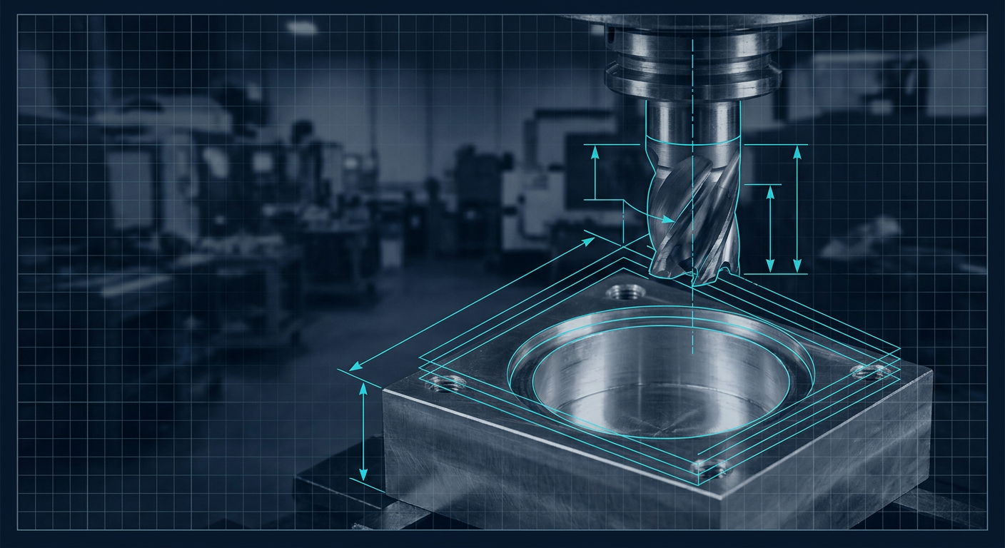
If you feed a triangle mesh from a standard 3D generative model into Mastercam or Fusion 360 to program a 3-axis mill, you know the immediate disaster that follows. A cylinder is not a cylinder. It is a cluster of 80,000 planar facets. When you click on the hole to set up a standard canned cycle like G81 or a helical bore, the CAM software cannot find a centerline. It cannot calculate a nominal radius. It sees hundreds of tiny flat faces stitched together with rounding errors. If you force a toolpath across it, the machine stutters through thousands of linear G1 micro-moves, cutting a faceted polygon instead of a true circle, destroying your tool life and ruining the bore tolerance before you even touch a micrometer.
For mechanical engineers, machine designers, and job shops, 3D meshes (STL, OBJ, or USDZ) are decorative junk. Unless a generative tool outputs true Boundary Representation (B-Rep) geometry with analytic surfaces, planes, cylinders, tori, and a clean parametric feature tree that exports cleanly to a STEP or Parasolid file, it has zero utility in a production workflow.
Over the past six months, text-to-CAD tools have started claiming they have solved this problem. Instead of generating point clouds or signed distance fields (SDFs) and running marching cubes, platforms like Zoo.dev (with its text-to-CAD API and Zookeeper agent) and Leo AI claim to output native, editable B-Rep models directly compatible with engineering workflows.
We put them on the bench. We ran three specific mechanical test cases through their generation pipelines: a press-fit bearing bore for a standard 608 ball bearing, a NEMA 17 flanged motor mount with a bolt circle pattern, and a parametric bracket requiring a wall-thickness modification. The goal was to see whether these tools produce genuine engineering geometry or if they merely wrap low-resolution approximations inside a STEP container.
The Architecture: Why Mechanical CAD Breaks Generative AI
To understand why generative geometry fails so hard on mechanical parts, you have to look at the mathematical difference between how computer vision models see 3D objects and how CAD kernels build them.
In computer graphics and generative text-to-3D models, geometry is dense, approximate, and continuous. An AI model trained on image diffusion or neural radiance fields treats 3D space like a voxel grid or a statistical density field. If a flat face bows outward by 0.15 mm or an edge has a tiny self-intersection, a rendering engine does not care. It shades the pixel, applies a texture map, and moves on.
A mechanical CAD kernel (like Parasolid, ACIS, or Open CASCADE) is an exact mathematical engine. A plane is defined by a point and a normal vector: zero thickness, zero curvature. A cylindrical hole is an analytic surface of revolution defined by a line axis and a precise radius $r$. An edge is an explicit intersection curve between two topological faces. If two faces meet at an angle of 89.98 degrees instead of 90.00 degrees, every downstream datum, mate constraint, and draft angle calculation downstream fails.
There are two main research approaches to making AI generate CAD:
Direct B-Rep Generation via Neural Networks: Academic models like DeepCAD (generating command sequences) and BRepGen (using Graph Neural Networks) attempt to predict topological graphs and boundary curves directly. This is mathematically difficult because the model must simultaneously predict discrete topology (which face connects to which edge) and continuous geometry (exact coordinates, radii, and knot vectors) without introducing non-manifold edges, self-intersections, or sliver faces.
Code-Generation / Domain-Specific Language (DSL) Compilers: The AI acts as a deterministic code-writing agent. Instead of spitting out boundary vertices directly, the large language model writes human-readable CAD code in a programmatic language (such as KittyCAD/KCL in Zoo.dev, Python in CadQuery, or OpenSCAD). That code is passed directly to an exact geometry kernel that compiles the script into precise B-Rep solids.
Zoo.dev has pivoted heavily toward this second path with its KCL (KittyCAD Language) and its Zookeeper conversational environment, abandoning pure direct neural B-Rep prediction. Leo AI similarly focuses on parametric intent, searching engineering constraints and generating structured feature definitions.
Let us look at how both approaches survive contact with the shop floor.
Test 1: The 608 Bearing Pocket (22 mm Nominal Bore)
A standard 608 skateboard/electric motor ball bearing has an outer diameter of 22.000 mm. In an aluminum 6061-T6 housing, achieving a light press fit (ISO fit N6 or P6) requires a bore machined to 21.987 mm to 21.996 mm. For a transition fit (H7), the bore must fall between 22.000 mm and 22.021 mm.
We prompted both systems with a clear engineering requirement: "Create an aluminum mounting block, 40mm x 40mm x 15mm thick. In the center of the 40x40 face, add a 22mm diameter through-bore for a 608 bearing, with an internal retaining shoulder 18mm diameter located 10mm deep. Add a 0.5mm x 45-degree chamfer to the top entry hole."
The Result from Zoo.dev (KCL Engine)
Zoo generated a KCL script that defined a 2D sketch on the XY plane, drew a 40x40 mm rectangle centered at the origin, and extruded it 15 mm along the Z-axis. It then executed a secondary sketch on the top face, drew a 22 mm circle, and performed a boolean cut to a depth of 10 mm. It then sketched the 18 mm circle on the bottom floor of that pocket and cut through the remainder of the block.
When we exported the STEP file and imported it into our inspection software:
- The bore was an exact analytic cylinder. The CAD kernel recognized it as a single topological face with a radius of precisely 11.000 mm (diameter 22.000 mm).
- The centerline was fully detectable by the CAM software. Setting up an automated hole-milling cycle took one click.
- The retaining shoulder was flat, parallel to the bottom face within zero numerical tolerance.
- Where it struggled: The 0.5 mm chamfer. While KCL supports fillets and chamfers, the language model frequently failed to resolve the topological edge index correctly, either omitting the chamfer entirely or generating a script error where the chamfer call referenced an invalid edge ID. We had to fix the KCL script manually by selecting the top circular edge.
The Result from Leo AI
Leo took the prompt and attempted to match design intent with parametric feature templates.
- The exterior envelope (40x40x15 mm) was accurate and generated as a clean rectangular prism.
- The 22 mm bore was modeled correctly as an analytical cylinder, not a faceted mesh.
- The stepped bore was structured as two distinct concentric hole features.
- Where it struggled: Leo struggled with the explicit depth assignment of the internal shoulder. It set the first bore depth to 7.5 mm (defaulting to half-thickness) instead of the prompted 10 mm depth, requiring manual override in the parameter table.
Tolerancing Reality Check
Neither system understands machining tolerances (like writing an ISO H7 fit directly into the geometry). Both systems generate nominal geometry (exactly 22.000 mm). If you send this STEP file straight to a machine shop without modifying it, your machinist will machine it nominal, and your bearing will either be too loose or require excessive force to press in, depending on tool deflection and thermal expansion. You still have to open the model in your CAD tool or edit the code to add your negative 0.012 mm stock offset for the press fit.
Test 2: NEMA 17 Motor Mount with Tapped Bolt Circle
A standard NEMA 17 stepper motor has a 31 mm square bolt circle (a 43.84 mm pitch circle diameter) with four M3x0.5 threaded holes spaced around a 22 mm central pilot boss.
We prompted the tools: "Design a 50mm square mounting plate, 6mm thick. Center pilot hole 22.5mm diameter through. Four M3 clearance holes on a 31mm square pitch centered on the pilot. Include a 2mm deep, 43mm diameter circular pocket on the rear face to clear the motor faceplate."
+----------------------- 50.0 mm -----------------------+
|                                                       |
|       (M3)                                (M3)        |
|         +---------------- 31.0 mm ----------+         |
|         |                                   |         |
|         |             .-'"""'-.             |         |
|         |           .'         '.           |         |
|         |          /   22.5 mm   \          |         |
|         |         |   (Pilot)     |         |         |
|         |          \             /          |         |
|         |           '.         .'           |         |
|         |             '-.....-'             |         |
|         |                                   |         |
|         +---------------- 31.0 mm ----------+         |
|       (M3)                                (M3)        |
|                                                       |
+-------------------------------------------------------+
This test exposes how AI handles 2D sketch constraints and symmetric relationships.
Zoo.dev Output
Zoo wrote a declarative KCL script calculating the four hole positions using basic trigonometry (x = 31/2, y = 31/2, etc.).
// Excerpt of generated KCL logic
const plateWidth = 50
const plateThickness = 6
const pilotRadius = 22.5 / 2
const pcdOffset = 31 / 2

fn holePattern = (sketch) => {
  // Generates circles at (+/- 15.5, +/- 15.5)
  return sketch
}
The resulting STEP file had fully concentric holes, correct bolt spacing (verified at exactly 31.000 mm center-to-center across all four holes), and clean planar faces. The rear 43 mm counterbore was cut cleanly without self-intersections.
However, because the code calculated static coordinate locations rather than creating a geometric "Circular Pattern" feature, modifying the pitch diameter later required changing four individual coordinates in the script instead of updating a single diameter variable. It lacked true parametric associativity unless explicitly prompted to use variables.
Leo AI Output
Leo approached this through engineering feature definitions. It recognized the NEMA pattern context and laid out the four holes as a patterned group.
Importing the resulting geometry into Onshape and SolidWorks showed clean feature recognition: the four holes were grouped, and changing the pitch spacing in the parameter tree adjusted all four holes simultaneously.
However, the clearance hole diameter was set to 3.000 mm (exact nominal screw diameter) rather than standard close clearance (3.2 mm) or free clearance (3.4 mm) according to ISO 273. An engineer taking this file to production would find that an M3 socket head cap screw will not pass through the hole due to minor thread runout and plating thickness.
| Feature Evaluated | Zoo.dev (KCL Engine) | Leo AI | Standard Mesh Gen (Point-E / Shap-E) |
|---|---|---|---|
| Geometry Representation | Pure B-Rep (STEP / KCL) | Pure B-Rep (STEP / Native) | Dense Triangle Mesh (STL/OBJ) |
| Analytic Surfaces | Yes (Exact Cylinders/Planes) | Yes (Exact Cylinders/Planes) | No (Faceted Approximations) |
| Hole Centerline Detection | Immediate in CAM | Immediate in CAM | Fails / Requires Manual Reconstruction |
| Sketch Constraint Logic | Coordinate-based / Scripted | Feature/Pattern-based | None |
| Chamfer / Fillet Execution | Unstable (Edge ID Errors) | Moderate (Standard Features) | Degraded / Rounded Surface Noise |
| Production Ready for CNC? | Yes, with manual offsets | Yes, with manual offsets | Absolutely Not |
Test 3: Parametric Editability and Downstream Feature Tree
The biggest lie in early generative 3D was that "importing an STL into CAD and auto-converting to B-Rep" yields a usable model. If you use the standard "Convert Mesh to Solid" tool in SolidWorks or Autodesk Inventor, the system fits hundreds of tiny NURBS surface patches over the mesh. The resulting STEP file is uneditable. You cannot change a boss height, move a hole, or apply a clean fillet because the underlying surfaces are fragmented ribbons.
We evaluated what happens when you need to make an engineering change order (ECO) to an AI-generated part. We took an L-bracket with two gussets and attempted to thicken the structural wall from 3.0 mm to 5.0 mm to handle an increased shear load.
The Zoo.dev Workflow
Because Zoo.dev is driven by KCL code, the part is not a static solid: it is a deterministic program.
To change the wall thickness, we opened the KCL editor in Zoo Design Studio. The wall thickness was defined at the top of the file as const wallThickness = 3. We changed 3 to 5 and re-compiled. The entire solid regenerated in under two seconds. The gussets maintained their geometric tangency to the inner walls, the mounting holes stayed centered on the mounting flanges, and the exported STEP file updated cleanly without topology errors.
This is where code-based CAD outclasses direct neural generation. Because the geometry is derived from explicit programmatic math, parametric relationships do not "drift" or warp like neural weights do.
The Leo AI Workflow
Leo provides a web-based parametric interface where major dimensions appear as editable fields.
We modified the thickness parameter. The model updated its external boundary cleanly. However, one of the structural gussets lost its mate alignment with the vertical upright, resulting in a 0.2 mm air gap between the gusset face and the bracket wall. This is a classic CAD kernel topology re-identification bug: when an extrude changes thickness, the face index shifts, and downstream sketch planes attach to the wrong face.
In our internal testing of generative mechanical kinematics at Mexaio AI, we see this exact boundary condition constantly: the AI can build the primary geometry, but complex multi-body assemblies and kinematic links require rigid mathematical constraint tracking that standard statistical language models fail to resolve without strict symbolic validation.
The Real Bottleneck: What AI Cannot See
While text-to-CAD has finally escaped the mesh trap and can now output valid STEP files with analytic cylinders and planar faces, several massive blind spots prevent these tools from operating autonomously in production environments.
1. Standard Thread Callouts and Tapping Drills
Neither tool produces native cosmetic thread metadata or standards-compliant tapped hole geometry. If you prompt for an "M6x1.0 tapped blind hole 12mm deep," both systems simply generate a 6.000 mm diameter cylinder extruded 12 mm deep with a flat bottom.
In real machining:
- An M6x1.0 tap requires a 5.0 mm pre-drill hole.
- A standard twist drill creates a 118-degree or 135-degree conical bottom point.
- Blind tapped holes need tap drill relief depth (at least 2 to 3 thread pitches beyond the usable thread) so the bottoming tap does not pack chips and snap off in the hole.
If a shop blindly runs a toolpath from the raw generated STEP, they will try to push a thread mill or tap into solid material or clear out the full nominal thread diameter, completely ruining the thread engagement.
2. Tool Clearance and Radii Constraints
AI models love internal square corners. When prompted for an internal rectangular pocket, both tools generate vertical internal corners with zero radius ($R=0$).
A CNC end mill cannot cut a sharp internal vertical corner. You need an inside corner radius larger than the cutting tool radius (for instance, specifying a 3.5 mm radius if using a 6 mm end mill to prevent tool chatter and corner dwell). Neither platform automatically applies manufacturing tool clearance rules to internal pockets unless explicitly instructed in the text prompt.
3. Datum Structure and GD&T
Mechanical parts do not exist in isolation. They mount to subassemblies with primary, secondary, and tertiary datums (Datum A, B, C).
When a human engineer designs a bracket, they align the origin with the locating face or the main dowel pin hole so that tolerances stack up predictably from that reference. Text-to-CAD tools place sketches arbitrarily on default global origin planes ($X=0, Y=0, Z=0$). This makes assembly mating in SolidWorks or Siemens NX frustrating because the native reference planes rarely align with functional mating surfaces.
Where Text-to-CAD Actually Fits Today
If you expect to type "Design a multi-stage planetary gearbox for a 500W brushless motor with a 10:1 reduction ratio" and receive a production-ready STEP file with correct gear tooth profiles, backlash compensation, and press-fit bearing seats, you will be disappointed. That level of synthesis is years away.
Where these tools deliver real leverage today is in first-stage volumetric modeling and parametric boilerplate:
- Rapid Bracket and Flange Generation: Typing a prompt to generate a 4-hole mounting flange with specific center-to-center spacing and an offset boss takes 10 seconds. It writes the initial KCL or parametric tree faster than a human can click through sketch planes, draw rectangles, apply dimension constraints, and extrude.
- Code-Driven Part Families: Zoo.dev's KCL approach allows engineers to build programmatic CAD libraries using standard software engineering practices (Git version control, continuous integration testing for CAD files, programmatic sizing scripts) without opening heavyweight desktop GUI applications.
- Geometry-Aware Semantic Search: Leo AI's ability to search internal engineering databases using geometric intent rather than brittle file-naming conventions solves a massive cataloging problem for large engineering teams.
For machine shops and robotics startups, the shift from triangle meshes to native B-Rep code is the dividing line that makes generative CAD worth watching. The output is no longer non-functional visual noise. It is real mathematical geometry that you can actually import into CAM, inspect on a CMM, and modify without rebuilding from scratch.
If you want to evaluate these tools in your own shop, stop prompting for generic visual shapes like helmets or sports cars. Prompt for an aluminum mounting block with a 28 mm bore, four counterbored clearance holes, and an internal O-ring seal groove. Export the STEP file, drop it into your CAM package, and see if your automated hole cycles pick up the geometry without manual repair. That single test will tell you everything you need to know about where the software stands.
Sources
- https://zoo.dev/zookeeper
- https://zoo.dev/research/zookeeper
- https://zoo.dev/blog/why-ai-must-generate-parametric-cad
- https://zoo.dev/
- https://www.getleo.ai/blog/text-to-cad-tools-comparison-guide
- https://www.getleo.ai/blog/open-source-text-to-cad-tools-free
- https://mikekalil.com/blog/ai-driven-text-to-cad/