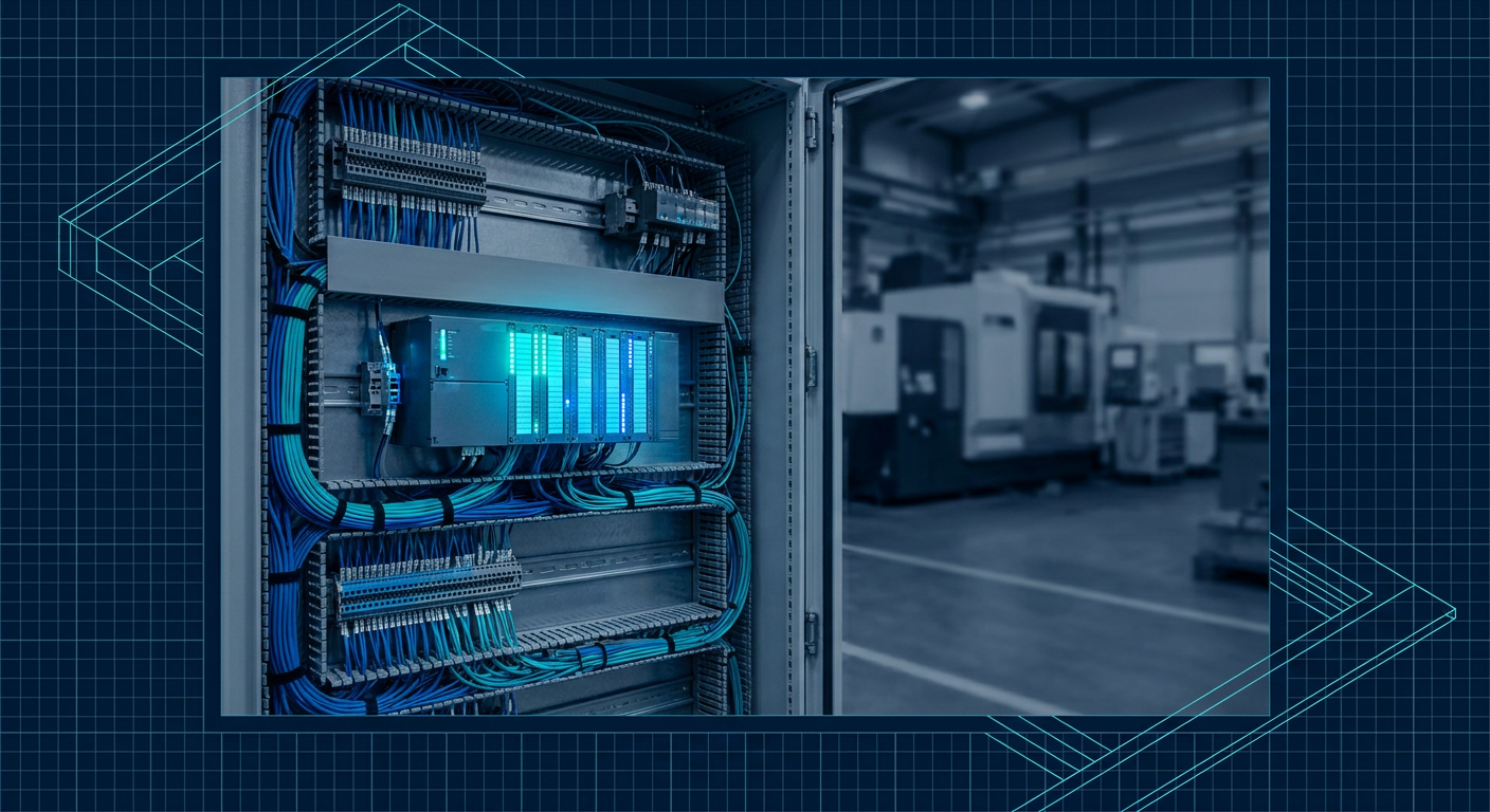
Schneider Electric launched its Industrial Copilot alongside a wave of specialized startups like PLC Copilot and PLCAutoPilot. You can now feed a functional description into an interface, wait eight seconds, and get back syntactically valid Structured Text, Siemens TIA Portal SCL, or Rockwell Studio 5000 ladder logic rungs. For a mechatronics engineer who designs mechanical linkages, sizes servomotors, and only opens an automation IDE when forced to bring a custom test bench to life, this feels like an immediate shortcut.
You paste the generated code into your controller software. It compiles with zero syntax errors. The logic looks structured. You download it to a Siemens S7-1200 or an Allen-Bradley CompactLogix, turn on the 24V field power, and hit start. Within thirty seconds, a pneumatic slide gets stuck midway through its stroke, an alarm refuses to clear, or two opposing motor contactors briefly fight each other across a shared bus.
The code compiled, but the physical machine seized.
Large language models understand grammar, syntax, and standard programming patterns. They do not understand the cyclic execution scan of an industrial programmable logic controller, nor do they understand the messy, asynchronous nature of industrial hardware. If you are using generative tools to write your routines, you need to know exactly where these models break down before you flash logic onto a live control box.
The Fundamental Disconnect: Scan Cycles vs. Sequential Code
Most generative AI models are trained on millions of lines of Python, C++, and JavaScript. Software written in standard high-level languages generally executes sequentially from top to bottom, waiting for functions to return, spinning on event loops, or running asynchronous tasks managed by an operating system thread scheduler.
PLCs do not work that way.
A PLC runs an endless, rigid loop called the scan cycle. A typical cyclic task performs three steps in order:
- Read all physical inputs and map them into an input image table.
- Execute the user logic sequentially from first rung to last rung.
- Write the calculated values from the output image table to the physical output terminals.
This cycle repeats continuously, typically every 5 to 20 milliseconds depending on your CPU load and task configuration.
When an LLM writes Structured Text, it frequently generates code that treats variables as if they update immediately across the entire universe of the program, or it uses loops that block the scan. If an AI writes a WHILE loop waiting for a proximity switch tag to transition from FALSE to TRUE, it creates an immediate CPU fault. In a standard language, a thread might yield or poll. In a PLC, a WHILE loop waiting for external hardware input inside a single scan will exceed the task watchdog timer (typically 100 to 500 milliseconds), crash the CPU, and trip the master safety relay.
Copilots know enough syntax to avoid basic WHILE traps in ladder, but they regularly fail on nuanced variations of scan-dependent logic. They often evaluate a condition at rung 4, modify an internal tag at rung 12, and expect an output at rung 2 to reflect that change within the exact same scan.
The Asynchronous I/O Trap
Modern industrial controllers, especially the Rockwell Logix family (ControlLogix and CompactLogix), do not use synchronous input image tables by default. They update I/O asynchronously to the program scan based on a Requested Packet Interval (RPI).
If you have a remote I/O drop over EtherNet/IP running at an RPI of 2 milliseconds, and your main continuous logic task takes 10 milliseconds to run, the physical input tag can change values three or four times while your code is halfway through executing its rungs.
Here is a common failure pattern produced by AI copilots:
// AI-Generated Sequence Logic
IF Sensor_PartPresent AND NOT Cylinder_Extended THEN
    Valve_Extend := TRUE;
END_IF;

// Ten lines of intermediate math and check logic

IF NOT Sensor_PartPresent AND Valve_Extend THEN
    Valve_Extend := FALSE;
    Error_PartLost := TRUE;
END_IF;
If Sensor_PartPresent is an asynchronous input tag connected to an optical sensor on a conveyor, it can flip from TRUE to FALSE between those two code blocks if the remote I/O packet arrives mid-scan. The controller turns on the valve in the first block, sees the sensor drop in the second block within the same millisecond, faults the line, and leaves the cylinder in a half-fired state.
Experienced controls engineers prevent this by mapping all raw field I/O into synchronous buffer tags at the very start of the routine:
// Correct Engineering Practice: Buffer Mapping
Local_PartPresent := Field_IO_Rack1_Slot2_Input.0;
Local_PartAtStop  := Field_IO_Rack1_Slot2_Input.1;

// Execute state logic ONLY against Local_ buffered tags
Copilots rarely generate this I/O buffering architecture unless you explicitly instruct them to do so in the prompt. They bind raw physical tag names directly into conditional state branches, setting up intermittent race conditions that are nearly impossible to catch on a quiet test bench and only trigger when the factory floor is running at full line speed.
State Machine Deadlocks and Edge Detection
Most industrial machinery moves through states: IDLE, FEEDING, PRESSING, INSPECTING, EJECTING, FAULT. Mechatronics engineers usually structure this as a numeric state machine using a CASE statement in Structured Text or integer step rungs in Ladder Logic.
LLM-generated state machines look clean on paper, but they systematically struggle with three edge cases: missed transition pulses, dual-step transitions, and unhandled fault recovery.
CASE Current_State OF
    0: // IDLE
        IF Start_Button_Pressed THEN
            Current_State := 10;
        END_IF;

    10: // ADVANCE CYLINDER
        Valve_Extend := TRUE;
        IF Cylinder_Extended_Switch THEN
            Valve_Extend := FALSE;
            Current_State := 20;
        END_IF;

    20: // RUN MOTOR
        Motor_Run := TRUE;
        IF Motor_Done THEN
            Motor_Run := FALSE;
            Current_State := 0;
        END_IF;
END_CASE;
This simple snippet contains several flaws that an AI will routinely generate:
- Lack of Entry/Exit Logic: If the system is in State 10 and an E-stop drops the 24V supply to the valve,
Current_Stateremains 10. When power is restored, the PLC immediately attempts to drive the valve without re-verifying safety permissives or homing the actuator. - One-Shot and Trigger Mismanagement: If
Start_Button_Pressedis a momentary push button, copilots frequently omit one-shot instructions (R_TRIGin IEC 61131-3, orONSin Rockwell). If the operator holds their finger on the button for 500 milliseconds, the machine runs through the entire sequence and immediately re-triggers State 10 instead of returning to a stable IDLE state. - Unhandled intermediate values: If noise on a field cable or an uninitialized tag forces
Current_Stateto an undefined value like 15 or 99, the state machine silently freezes. The code compiles, but the physical machine stops responding to any input. A human programmer writes anELSEcondition that catches invalid states and forces a controlled fault routine; an AI rarely includes it unless specifically prompted.
Hardware Timers and Physical Latencies
When software engineers write unit tests, functions execute in microseconds. On a machine tool, physics dominates.
A pneumatic solenoid valve takes 15 to 40 milliseconds to shift its internal spool. The cylinder takes 300 milliseconds to stroke. The reed switch at the end of the stroke bounces for 8 milliseconds before settling into a clean 24V high signal. A hydraulic pump needs three seconds to build system pressure before a clamp can safely hold a workpiece.
Generative AI models often treat digital inputs as immediate mathematical truths. They link the command directly to the verification sensor without debounce timers (TON or TOF).
If you tell a copilot, "Write a routine that advances a cylinder, verifies it reached the end, and then starts a spindle motor," it often writes code that transitions the state the exact microsecond the reed switch flickers on. The reed switch bounces, the controller sees the input go low again for two milliseconds, the state machine enters an unrecoverable fault state, and the spindle never fires.
To make copilot logic work in the real world, you must wrap every physical sensor transition in a debounce timer or write explicit travel-time watchdogs. The logic must say: "If the extend command is active, and the end switch has been solidly on for at least 50 milliseconds, proceed. If the end switch does not turn on within 1.5 seconds, abort and signal a cylinder travel fault."
| Failure Mode | What the AI Generates | What the Hardware Actually Needs |
|---|---|---|
| Sensor Bouncing | Direct evaluation: IF Input_Sensor THEN |
Standard on-delay timer (TON) with 10-50ms debounce |
| Actuator Jamming | Waits infinitely for limit switch | Travel watchdog timer that throws an alarm after timeout |
| Power Cycle / Reset | Retains active state integer in non-volatile tag | First-scan routine (S:FS or System_Flags.First_Scan) forcing safe init |
| Fieldbus Disconnection | Reads stale data values in buffer | Comm health check evaluating packet counter before logic |
The Blurred Line Between Control Logic and Safety Logic
Mechatronics engineers know they need emergency stops, interlocked light curtains, and safety door switches. But if you do not spend every week calculating Performance Levels (PLr under ISO 13849-1) or Safety Integrity Levels (SIL under IEC 62061), you might be tempted to let a copilot write your safety bypasses or fault monitoring.
This is a severe liability.
Standard PLC code generated by an LLM is non-deterministic software executing on non-safety-rated memory partitions. You cannot use AI-generated ladder logic to replace a dual-channel safety relay or a dedicated Safety PLC program (such as a Rockwell GuardLogix or Siemens F-CPU safety task).
Copilots often suggest code like this:
// DANGEROUS: Mixing functional control with safety interlocks
IF E_Stop_Pressed OR Guard_Door_Open THEN
    Motor_Enable := FALSE;
    Brake_Release := FALSE;
END_IF;
If an internal tag gets overwritten by another subroutine, or if an output transistor fails in a short-circuit state, this logic does nothing to stop the machine. Safety logic must be physically wired to force-guided relays, cut safe torque off (STO) lines on drives directly, and run in safety-certified tasks that use cross-monitoring.
Never ask an AI copilot to write logic that touches a safety tag. Use it only for standard sequencing, material handling, calculations, and operational diagnostics.
What Industrial AI Copilots Actually Do Well
AI copilots are not useless. Used correctly, they save hours of tedious manual entry, especially if you are not in the PLC editor every day. You just have to restrict them to tasks where syntax and structure matter more than real-time hardware physics.
1. Boilerplate Add-On Instructions (AOIs) and Function Blocks
Writing repetitive routines for standard equipment is where copilots shine. If you need a function block that scales a raw 4-20mA analog input (0 to 27648 on Siemens, or 0 to 16383 on older Rockwell cards) into engineering units like bar, liters per minute, or degrees Celsius with high/low alarms, an LLM will write that code perfectly on the first pass.
2. Translating Between Controller Dialects
Moving from Siemens TIA Portal SCL to Beckhoff TwinCAT Structured Text or CODESYS 3.5 is annoying. Variable declarations, array bounds, and timer syntax differ slightly across vendors. Feeding working Siemens SCL into a copilot and asking for IEC 61131-3 compliant Structured Text for a WAGO or CODESYS-based controller works reliably because it is purely a syntax translation task.
3. Alarm and Diagnostic Text Generation
Creating long lists of alarm tags, mapping fault codes to human-readable strings, and generating comments for every rung takes hours. AI tools can take your state machine tag list and instantly generate matching alarm messages, HMI alarm tables, and rung documentation.
At LabCD (labcd.ai), we look closely at how control box layouts and automation code integrate into daily shop workflows. The consensus from testing these tools on physical panels is consistent: treat generative AI like a fast, tireless junior intern who knows all the syntax manuals by heart but has never smelled a burning motor coil or seen an air cylinder bend an aluminum bracket.
The Verification Protocol: What to Do Before Flashing Code
If you use an AI copilot to draft your routine, never compile it and download it directly to a live machine. Run this five-step verification checklist on your workbench first.
Step 1: Isolate and Buffer Your I/O
Search the generated logic for any direct references to physical hardware addresses or network fieldbus I/O tags. Strip them out.
Create a dedicated mapping routine at the beginning of your project tree. Map your physical inputs to an internal User-Defined Type (UDT) or structured tag (Local_In.PartPresent). Run the copilot's logic exclusively against those internal tags. Map the results back to an output buffer at the end of the scan. This eliminates mid-scan race conditions instantly.
Step 2: Test the State Machine Matrix
Draw a grid of every state your machine can enter. For every state, verify three things:
- What happens if the primary transition sensor never fires? (Add a travel timeout).
- What happens if the power drops or the stop button is hit while in this state? (Verify the machine cannot resume motion without a deliberate home sequence).
- Does the state machine contain a catch-all condition to recover from invalid numbers?
// Always include an unhandled state trap
ELSE
    Fault_Code := 9999; // Invalid state detected
    System_Fault := TRUE;
    Current_State := 999; // Lock to safe fault state
Step 3: Run the Code in a Software Emulator
Do not test new logic on physical hardware with live 480V three-phase or 90 PSI compressed air connected. Use software simulation tools like Rockwell FactoryTalk Logix Echo, Siemens PLCSIM Advanced, or TwinCAT PLC Simulation.
Force your inputs manually. Toggle a limit switch on, see if the outputs fire as expected, and then intentionally toggle the switch off at the wrong time. Watch how the state machine behaves when you feed it illegal sensor combinations, such as both the Cylinder_Retracted and Cylinder_Extended switches reporting TRUE simultaneously due to a damaged sensor cable.
Step 4: Add Sensor Debouncing and Motion Timeouts
Look at every sensor transition in the logic. If the copilot wrote IF Sensor_Tripped THEN, replace it with an explicit timer block (TON). Set the preset value (PT or PRE) to at least 20 to 50 milliseconds to filter out mechanical vibration, chatter, and electromagnetic noise from adjacent contactors.
// Debounce timer instantiation
Debounce_PartSensor(
    IN := Raw_PartSensor_Input,
    PT := T#50MS
);

IF Debounce_PartSensor.Q THEN
    // Proceed with verified state transition
END_IF;
Step 5: Physically Disconnect Actuator Power for First Motion Tests
When you finally download the verified code to the real controller in the panel, keep the high-voltage motor circuit breakers and main pneumatic dump valves locked out.
Watch the status LEDs on your digital output slices (such as a 16-channel 24V DC transistor card). Step through the machine operations manually. Verify that the correct output LED turns on and stays on only when the proper mechanical conditions are met. Only introduce pneumatic pressure and motor drive power once you have verified every sequence step visually on the panel LEDs.
Practical Steps for Your Next Project
If you have inherited a control box or need to automate a custom bench this month, start small with AI tools.
Use them to write your math scaling, your data logging structures, and your initial state machine drafts. But write your own I/O buffering, design your own fault recovery paths, and keep all safety functions on hardwired, dedicated safety hardware.
Keep a text file of verified template blocks that you know work reliably on your specific hardware. When you ask a copilot to generate new logic, feed it your verified template as part of the system prompt. Tell it explicitly to use synchronous tag buffering, include debounce timers, and avoid blocking loops. You will spend less time troubleshooting frozen state machines on a cold shop floor, and you will get the speed benefit that these copilots were built to deliver.
Sources
- https://blog.se.com/digital-transformation/artificial-intelligence/2025/11/14/engineering-at-scale-how-ai-is-transforming-plc-coding/
- https://www.automationworld.com/process/digital-transformation/article/55305398/schneider-electric-inside-the-new-industrial-copilot-with-schneider-electrics-aurelien-lesant
- https://plccopilot.com/
- https://www.plcautopilot.com/