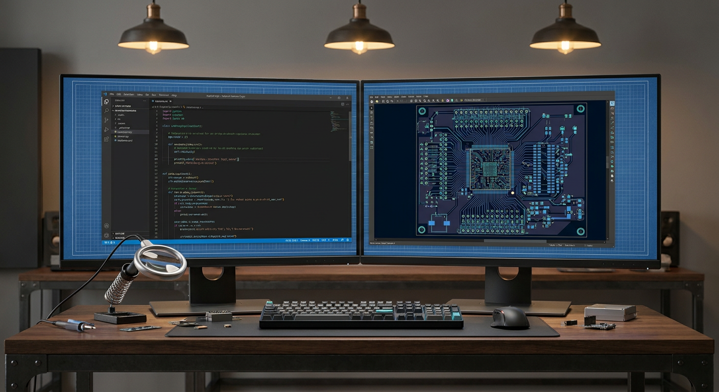
If you manage Git repositories containing KiCad or Altium files as a solo hardware engineer, you already know the sinking feeling of opening a pull request. Two branches touched the power distribution sheet. In KiCad, that means comparing thousands of lines of sexpr text where pin coordinates shifted by 2.54 millimeters. In Altium, it means binary conflicts or visual diff tools that fail to tell you if an electrical connection actually broke or if someone simply moved a capacitor symbol to make room for a net label.
Schematic capture has remained visually anchored for forty years. We draw boxes, place pins, string green lines between them, and compile an export netlist for the layout editor. Tools like Atopile and JITX take a radically different stance: eliminate visual schematic sheets entirely and write your board in code.
Treating hardware like software is an old promise. VHDL and Verilog succeeded for digital logic decades ago, but board-level analog and mixed-signal design resisted text representations. Modern compiled hardware tools want to change that. They let you declare components as classes, wire interfaces together using dot notation, assign parametric constraints, and generate netlists or KiCad board files directly from your terminal.
To see if this workflow is ready for production boards, we put the code-first approach through the standard tasks that take up a hardware engineer's week: parametric power supply reuse, diffing revisions, managing supply chain alternates, and debugging on the bench.
How Code-First Hardware Actually Works
Traditional schematic capture is spatial. You place an IC symbol, look up the pinout in the PDF datasheet, place passive components around it, and hook them up.
In Atopile, you write structured declarations in a domain-specific language that feels like Python crossed with a declarative configuration file. A voltage divider or a buck converter is not a drawn cluster of symbols. It is a module with typed electrical ports.
# Example Atopile snippet
component Resistor:
    pin 1
    pin 2
    electrical resistance

module VoltageDivider:
    power_in = new Power
    power_out = new Power
    ground = new Ground

    r_top = new Resistor
    r_bottom = new Resistor

    power_in.vcc ~ r_top.pin1
    r_top.pin2 ~ power_out.vcc
    power_out.vcc ~ r_bottom.pin1
    r_bottom.pin2 ~ ground.gnd

    # Assert output voltage constraint
    power_out.voltage == power_in.voltage * (r_bottom.resistance / (r_top.resistance + r_bottom.resistance))
JITX operates on similar principles using a specialized dialect of Lisp and high-level Python-style APIs. Rather than manually picking every resistor value from a catalog, you write programmatic rules. You specify that a rail needs 3.3V at 1.5A from a 12V input with less than 30mV ripple. The compiler calculates component values, selects real orderable parts from vendor databases, checks footprint compatibility, and outputs a routed or pre-placed layout file.
This is fundamentally different from a netlist generator. The compiler performs electrical rule checks (ERC) at build time. If you connect a 3.3V GPIO to a 5V input without a level shifter, the compiler throws a type error and halts the build before you ever open the PCB layout editor.
The Real Value: Parametric Sub-Circuits and Reuse
Design reuse in graphical EDA is notoriously fragile. Every engineer has a personal library of "known-good" snippets: a USB-C input stage with ESD protection, an STM32 minimal footprint with decoupling, or a Texas Instruments TPS62840 buck regulator circuit.
In Altium or KiCad, reusing that buck regulator requires copy-pasting the schematic block and importing the corresponding layout snippet. If your input voltage changes from 5V to 12V, you must manually open the datasheet, recalculate the inductor value and feedback resistors, find new passives that meet the voltage derating requirements, replace the footprints, and update the BOM.
With code-first tools, the regulator becomes a parametric class. You pass the operating parameters directly into the module instantiation:
buck = new TPS62840
buck.vin = 12V +/- 10%
buck.vout = 1.8V +/- 2%
buck.imax = 750mA
The module code runs the formulas from the datasheet internally. It selects an inductor with an adequate saturation current, picks standard 1% tolerance feedback resistors that yield the target voltage within your margin, and checks the capacitor dielectric ratings. If you decide to change the core rail from 1.8V to 1.2V in revision B, you change one line of code. The compiler recalculates the passive values, swaps the part numbers in your generated bill of materials, and verifies that the output ripple remains inside your defined tolerance.
For solo engineers handling multiple projects with common architectures, this level of automation cuts days out of the front-end design cycle. You stop doing algebra in spreadsheets on a second monitor.
Git Diffs and Collaborative Code Review
The clearest operational win for text-based circuit design is version control.
When you open a pull request for a KiCad project, the graphical schematic files produce unreadable diffs. If someone cleans up a schematic by moving a micro-controller block to the left, Git flags fifty modified lines of coordinate transforms. Real electrical changes get buried in cosmetic noise. Reviewing a schematic PR often requires checking out the branch locally, opening KiCad, and visually panning across five sheets to spot what changed.
With code-first tools, your pull request looks like standard software code:
 module PowerStage:
-    r_sense.resistance = 10mohm +/- 1%
+    r_sense.resistance = 5mohm +/- 1%
-    c_boot.footprint = "C0402"
+    c_boot.footprint = "C0603"
A reviewer sees instantly that you lowered the current-sense resistance to accommodate a higher trip threshold and bumped the bootstrap capacitor footprint to an 0603 package to handle higher voltage derating.
Continuous integration pipelines can build the board on every push. A GitHub Actions runner can run the Atopile compiler, verify all voltage constraints, confirm that every net has a source and a sink, ensure no bypass caps violate dielectric DC bias margins, and generate manufacturing outputs. If a junior engineer connects an unregulated battery line directly to an unrated pin, the automated build fails on the pull request.
Where the Code-First Abstraction Breaks Down
Code-first EDA solves many real pain points, but pretending hardware is identical to software introduces severe problems. Electronics are physical, analog, and spatial.
1. The Loss of Spatial Intuition
Schematics are not just wiring lists. A well-drawn schematic is an engineering map. An experienced engineer looks at a schematic page and immediately grasps signal flow, functional isolation, sensitive high-impedance nodes, and noisy power switching loops. The physical arrangement of symbols conveys intent.
When a circuit is written in code, that visual hierarchy disappears into nested text blocks. Tracing an analog signal chain through three class inheritances and four dot-notated interface bindings requires mental parsing that is often slower than scanning a single drawn page.
2. Lab Bring-up and Bench Debugging
When a prototype board comes back from assembly with a dead rail or an oscillating feedback loop, you do not debug it in a terminal. You sit at a bench with an oscilloscope, a DMM, and a printout of the schematic.
You look for test points, trace where pin 4 goes, find the physical pull-up resistor next to the switch, and tack on a bodge wire. If your EDA tool generates a schematic purely as an intermediate compilation artifact, the resulting auto-generated visual schematic is often an unreadable mess of stacked pins and tangled net labels.
Debugging a board without a human-readable visual schematic is painful. Until code-first tools can synthesize human-quality, cleanly organized schematics with logical signal flow, bench bring-up will remain a serious bottleneck for code-designed boards.
3. Supply Chain and Footprint Reality
Component availability is chaotic. When your primary buck converter goes out of stock during a production run, swapping it is rarely a pure software operation. You need to verify thermal pad geometries, pin pitches, inductors, compensation networks, and switch-node parasitics.
While JITX and Atopile have integrations to search part databases like JLCPCB, LCSC, or Octopart, hardware engineering edge cases remain tricky. An algorithm picking a substitute capacitor might match capacitance, voltage rating, and package size, but it might miss the ESR requirement necessary to keep a specific low-dropout regulator stable. Encoding every physical and chemical nuance of analog hardware into software classes requires massive, well-maintained component libraries.
The Layout Bottleneck
Schematics only account for roughly 30% of the total design effort on a dense, high-speed board. The hardest part is physical layout: component placement, trace routing, stackup design, impedance control, return path continuity, and thermal management.
Atopile deliberately does not try to replace the PCB layout editor. It compiles your code down to a netlist and a set of placement groupings, then exports them into KiCad. You still route your board by hand in KiCad's layout tool.
+-----------------------+
|  Atopile / JITX Code  |
|  (Classes, Logic,     |
|   Constraints)        |
+-----------+-----------+
            |
            v (Compiler / ERC)
+-----------------------+
| Netlist & Constraints |
+-----------+-----------+
            |
            v
+-----------------------+
| KiCad / Altium Layout |
| (Placement, Routing,  |
|  DRC, Layer Stackup)  |
+-----------+-----------+
            |
            v
+-----------------------+
| Gerber / ODB++ Output |
+-----------------------+
This split introduces synchronization friction. If you make a quick adjustment during layout, such as swapping two microcontroller GPIO pins to avoid five trace crossings on a dense BGA escape, you cannot easily push that change backward if your tool does not support full bi-directional back-annotation. You have to edit the code, recompile, and ensure your layout file updates without stripping your existing routed traces.
JITX attempts to automate placement and routing through algorithmic solvers. For simple breakout boards or standard microcontroller layouts, this works reasonably well. But for high-density interconnect (HDI) designs with differential pairs, length-matched DDR memory buses, and RF matching networks, algorithmic placement often requires so many manual constraint definitions that writing the constraints takes longer than routing the board by hand.
Autonomous tools like IntelCAD (intelcad.ai) tackle this layout complexity by combining AI-driven placement and constraint handling with existing design flows, but the industry is still working through the cleanest way to bridge high-level intent with low-level copper geometry.
Feature Comparison: Traditional EDA vs Code-First Tools
To see how the trade-offs stack up for a small hardware engineering team, we compared standard graphical workflows against current code-first tools across critical tasks:
| Capability | Altium Designer / KiCad | Atopile | JITX |
|---|---|---|---|
| Schematic Input | Graphical canvas (manual wiring) | Code DSL (.ato files) |
Code dialect (Lisp/Python syntax) |
| Version Control | Binary or complex sexpr diffs | Plain-text Git diffs | Plain-text Git diffs |
| CI/CD Integration | Limited (scripted headless exports) | Native CLI build and test | Native CLI build and test |
| Circuit Reuse | Snippets, sheet symbols | Parametric object classes | Parametric code modules |
| Layout Engine | Native interactive layout | Exports to KiCad PCB | Integrated programmatic layout |
| Part Selection | Manual via library/Octopart | Code-defined or package manager | Programmatic constraint solving |
| Bench Debugging | Excellent (human-drawn sheets) | Hard (auto-generated sheets) | Hard (auto-generated sheets) |
| Learning Curve | Visual, standard across industry | Requires software engineering mindset | Requires DSL and constraint logic |
When Does Writing PCBs in Code Make Sense?
Code-first PCB design is not an all-or-nothing proposition. It shines in specific applications and falls flat in others.
Where Code-First Wins Today:
- Modular, repetitive test fixtures and carrier boards. If you are designing a motherboard that breaks out thirty identical sensor channels, writing a loop in code that instantiates thirty channels with unique addresses and power rails takes minutes. Drawing thirty identical schematic sheets by hand is tedious and error-prone.
- Product families with variable configurations. If you build industrial controllers where Model A needs 4 relays, Model B needs 8 relays, and Model C needs 4 relays plus an isolated RS-485 transceiver, you can manage the entire family in a single codebase using conditional compilation flags.
- Teams with mixed software and hardware engineers. Software developers who need to design simple interface boards, compute carrier breakouts, or internal test jigs can build functional hardware using familiar text editors, package managers, and Git workflows without learning complex graphical EDA tool suites.
Where Graphical EDA Still Dominates:
- Dense, high-speed mixed-signal boards. When working with RF front-ends, high-speed SerDes lines, sensitive analog instrumentation amplifiers, or tightly packed wearable designs, physical placement dictates schematic topology. Writing code to represent circuits where copper parasitics, trace geometries, and ground plane splits dominate performance is counter-productive.
- Rapid prototyping on the bench. If you are building a quick one-off analog filter or breadboard companion, dragging four components onto a KiCad sheet and hitting print is still faster than defining classes, writing interface bindings, and compiling code.
- Subcontracted manufacturing and external reviews. Fab houses and contract manufacturers expect standard schematics for design reviews and DFM checks. Handing a contract manufacturer an auto-routed netlist with computer-generated schematics often leads to confusion and delayed assembly reviews.
How to Test Code-First Tools Without Breaking Your Pipeline
If you want to evaluate code-first circuit design without risking your next critical product milestone, start small.
Do not migrate your main product architecture on day one. Pick an internal test jig, a programming adapter, or a simple auxiliary power board.
- Install the CLI: Clone the Atopile repository and install the compiler inside your standard development environment.
- Build a known sub-circuit: Take a reliable power supply design from your library, such as a 5V-to-3.3V buck regulator. Write it as an Atopile module with input voltage, output voltage, and current parameters.
- Inspect the KiCad export: Compile the module and export it into KiCad. Open the resulting board file and look at the component grouping and net connections. Check whether the layout workflow feels intuitive or if missing schematic visual context slows you down.
- Set up a Git CI action: Commit the code to a repository and write a simple continuous integration script that verifies the design and outputs manufacturing files on every push.
Code-first design will not kill schematic sheets overnight. Hardware engineering has too many spatial and physical dependencies for text alone to replace visual tools entirely. But for parametric module reuse, automated design verification, and modern version control, code-based tools are solving real structural flaws in how we build electronics.