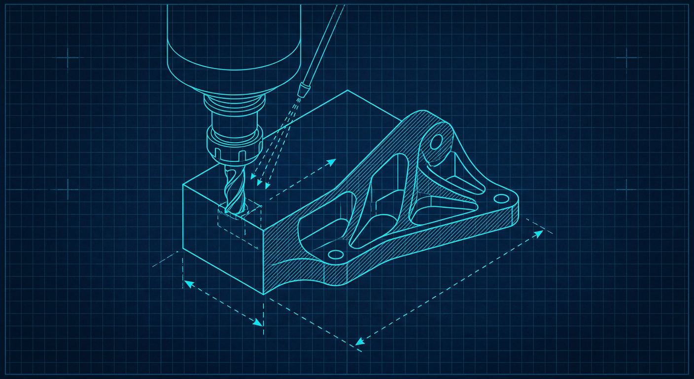
Every CNC programmer knows the feeling of opening a STEP file sent over by a junior design engineer who just discovered topology optimization. The part looks like an alien pelvis. It has hollow internal cavities with no entry vector, paper-thin structural webs floating in mid-air, compound curved fillets that require a custom 1.5 mm ball mill with a 75 mm reach, and zero flat datum surfaces for a Kurt vise.
Running that model on a three-axis vertical machining center is impossible. Running it on a five-axis trunnion table requires three custom sacrificial fixtures, five tool changes with necked tooling, and six hours of cycle time for a bracket that holds an idler pulley.
Generative design algorithms in CAD tools do what you tell them to do. If you tell them to optimize for stiffness-to-weight and leave the manufacturing constraint set to "unconstrained" or generic additive manufacturing, the solver relies on finite element math (usually Solid Isotropic Material with Penalization, or SIMP) to place mass along load paths. It does not know that a 1/2-inch flat endmill cannot cut a square corner. It does not know what tool chatter is. It does not care about your tooling budget.
To get parts that can be machined on a standard Haas VF-2 or a Doosan five-axis mill without ballooning part cost from $80 to $1,400, you have to constrain the solver before it ever runs its first iteration.
Why Solvers Default to Uncuttable Geometry
Topology optimization is inherently a voxel or mesh density problem. The solver discretizes a design space into thousands or millions of elements. Under applied loads, elements carrying low strain energy get stripped away; elements carrying high strain energy stay.
Additive manufacturing handles organic density distributions reasonably well because a laser powder bed or an FDM nozzle builds slice by slice from the bottom up. Material can exist anywhere as long as it has minimal self-supporting overhangs or support structures.
Subtractive manufacturing is the exact opposite. Material removal is constrained by physical tool access, spindle clearance, tool rigidity, and fixture clamping.
When you cut 6061-T6 or 7075 aluminum on a mill, four physical realities govern the cut:
- Tool aspect ratio ($L/D$). Once an endmill sticks out past three times its diameter ($3\times D$), deflection increases with the cube of length ($L^3$). At $6\times D$ or $8\times D$, you get severe chatter, ruined surface finish, and broken carbide.
- Tool geometry and fillets. An endmill is cylindrical. It cannot produce an inside vertical corner with a sharp radius. If the inside corner radius equals the cutter radius, the tool wraps around the corner with 90 degrees of cutter engagement, causing spike loads and chatter. The corner radius must always be slightly larger than the cutter radius.
- Line-of-sight clearance. The cutting tool, toolholder (such as an ER32 collet chuck or shrink-fit holder), and spindle nose must clear every part face along the tool path.
- Workholding and datums. A part must be held rigid against cutting forces of hundreds of newtons. If the algorithm strips away parallel flat faces, you have nowhere to grip the stock in a standard vise, forcing you into expensive soft jaws or additive nesting fixtures.
If your generative setup does not explicitly enforce these boundaries, the solver will produce geometry that exists only in rendering software.
The Real Mechanics of 3-Axis Constraints
Three-axis milling means the cutter approaches from a single fixed axis ($Z$) at any given setup. You can machine the top, flip the part over to machine the bottom (two setups), or use right-angle heads for side cuts, but the tool vector is static.
When setting up a three-axis milling constraint in modern generative solvers, you must define three core parameters: tool direction, minimum tool diameter, and tool shoulder length.
Tool Direction and Flip Vectors
In standard generative engines, setting a 3-axis constraint requires picking a pull direction. In Autodesk Fusion 360, this is defined by selecting a plane or coordinate axis (e.g., $\pm Z$).
If you select a single direction ($+Z$), the algorithm forces every pocket to be open from the top with zero undercuts. Every cut floor must be visible looking straight down the Z-axis.
If you enable both directions ($+Z$ and $-Z$), the engine models a two-setup operation: top machining and bottom machining after a flip. This creates through-pockets or opposed pockets with a central webbing.
Here is where engineers get caught: the solver will create deep, narrow ribs with straight 90-degree vertical walls. If that pocket is 50 mm deep and the solver chose a 4 mm width, you are looking at a 12.5:1 aspect ratio. No machinist can run a 4 mm endmill at 50 mm depth in aluminum without immediate tool breakage.
Setting Minimum Tool Diameter and Cut Depth
You must constrain the minimum tool diameter. Setting this parameter does two critical things in the solver:
- It sets the minimum inside radius of all vertical internal corners ($R \ge D/2$).
- It limits the narrowest slot or channel the solver is allowed to carve out.
For general production aluminum parts, do not set your minimum tool diameter below 6 mm (or 1/4 inch) unless the part is smaller than a matchbox. For larger structural parts (over 200 mm across), set the minimum tool diameter to 10 mm or 12 mm (1/2 inch). A 12 mm rougher can clear material at high metal removal rates (MRR), reducing machine cycle time from hours to minutes.
Tool shoulder length tells the solver how deep the tool can reach without the holder colliding with the stock. If your maximum pocket depth is set to 40 mm, the solver will refuse to carve narrow features deeper than 40 mm, preventing deep, inaccessible trenches.
2.5-Axis Milling: The Pragmatic Choice
Several modern solvers now include a specific 2.5-axis constraint option. Unlike pure 3-axis generative design, which generates sculpted 3D terrain on pocket floors, 2.5-axis constraints restrict the optimization to prismatic geometry: planar faces, vertical walls, and flat pocket floors at discrete depths.
2.5-axis generative design does not look as exotic on social media, but it is vastly cheaper to produce. Standard 2D adaptive clearing toolpaths can rough the entire part in one or two setups with high-feed endmills, followed by single-pass wall contouring. Cycle times drop by 60% to 80% compared to 3D surface ball-milling.
PTC Creo, Fusion 360, and Diabatix: How the Solvers Compare
Not all constraint engines handle subtractive rules with equal fidelity. Let us look at how the main generative design solvers implement manufacturing limits.
| Feature / Solver Capability | Autodesk Fusion 360 | PTC Creo (Frustum Engine) | Diabatix (ColdStream) |
|---|---|---|---|
| 2.5-Axis Prismatic Milling | Strong. Generates discrete flat pockets and profile extrusions. | Handled via extrusion constraints rather than dedicated 2.5D solver. | Not designed for prismatic CNC. Optimized for thermal/fluid channels. |
| 3-Axis Directional Limits | Explicit ($\pm X, \pm Y, \pm Z$). Excellent collision modeling for tool diameter. | Draft angle, parting direction, and tool pull constraints available. | Primarily additive and casting; thermal geometry must be manually adapted for milling. |
| 5-Axis Constraints | Allows simultaneous tool reach; can over-complicate 3+2 setups. | Multi-axis milling constraints with user-defined minimum web thickness. | High-performance thermal surfaces; requires heavy post-machining clean-up. |
| Draft Angle Enforcement | Limited in standard 3-axis milling (uses vertical walls); draft lives in casting mode. | Explicit draft angle inputs available during generative setup. | Not natively enforced for standard subtractive tooling paths. |
| B-Rep / Solid Export Quality | Exports editable T-splines or converted analytical B-Rep solids. | Generates native parametric B-Rep features with direct Creo geometry tree integration. | Exports high-resolution meshes (STL/STEP) requiring reconstruction for CAM. |
Autodesk Fusion 360
Fusion 360's generative engine is one of the most accessible for CNC programming because the CAM environment lives in the same workspace. You can generate a 3-axis outcome, export it as a solid body, and immediately switch to the Manufacture tab to apply toolpaths.
Its 3-axis milling solver is disciplined about tool access directions. If you set a 6 mm tool diameter and 30 mm maximum reach along the Z-axis, it strictly eliminates undercuts relative to that axis. However, its 5-axis solver is overly optimistic. It assumes a 5-axis machine can approach from continuous, infinitely variable angles, often generating undercut pockets that require continuous simultaneous 5-axis motion rather than simpler, stiffer 3+2 indexed positional cuts.
PTC Creo (Frustum Engine)
PTC integrated the Frustum generative kernel into Creo. Creo's standout strength is its direct integration with parametric CAD geometry. Instead of outputting a dense mesh that you struggle to snap dimensions to, Creo can generate B-Rep geometry with actual planar faces, cylinders, and draft angles.
Creo allows designers to combine milling constraints with parting line and draft angle parameters. By applying a 1-degree or 2-degree draft constraint along the pull direction, you create parts that are not only easier to machine with tapered endmills (or standard endmills using stepdown) but can also be transitioned to investment casting or forging later without redesigning the geometry.
Diabatix (ColdStream)
Diabatix specializes in thermal and conjugate heat transfer optimization rather than purely structural brackets. It generates liquid cold plates, heatsinks, and heat exchangers.
Because its primary optimization driver is fluid flow and thermal dissipation, its native outputs are heavily biased toward additive manufacturing or investment casting. If you want to mill a Diabatix-designed cold plate on a CNC router or 3-axis mill, you cannot simply let the algorithm build continuous internal fluid channels. You have to set boundary conditions that force channels to remain open from the top face, allowing a ball or bull-nose endmill to cut the fluid channels before a flat top plate is bolted or brazed on as a cover.
The Five-Axis Myth: Simultaneous vs. 3+2
A major trap in generative design is checking the "5-Axis Machining" box in the software because your shop happens to have a 5-axis machine on the floor.
Simultaneous 5-axis machining (where axes X, Y, Z, B, and C move together while the tool cuts) is expensive and mechanically demanding. Cutting forces are cantilevered away from the machine table base, reducing rigidity. Surface finishes cut with the tip or side of a ball endmill during simultaneous multi-axis sweeps require small stepovers (e.g., 0.1 mm to 0.3 mm), resulting in long cycle times.
Most practical 5-axis work in aerospace and robotics is not simultaneous 5-axis. It is 3+2 positional machining (indexed 5-axis). The machine tilts the trunnion to a fixed compound angle, locks the rotary brakes for maximum rigidity, and cuts the feature using standard 3-axis milling routines. It then indexes to another angle and cuts the next face.
When you configure a generative solver for 5-axis work:
- Do not use unconstrained 5-axis settings unless you are machining impellers, blisks, or complex turbine blades.
- In solvers that support multi-directional milling setups, define specific discrete tool directions (for example: Top, Bottom, and two 45-degree angled access vectors).
- Keep preserved geometry regions large enough to accommodate rigid fixture clamping or standard dovetail stock preparation.
If the generative solver creates an undercut that can only be reached with an extended ball mill tilted at a 37-degree compound angle while hovering 1 mm over an adjacent rib, your CAM programmer will reject the model.
Step-by-Step Setup Recipe for a Millable Bracket
Here is a baseline workflow to generate a structural aluminum bracket that can be cut on a standard 3-axis or 3+2 mill without tooling headaches.
Step 1: Define Preserve Geometry with Clamping and Fastener Access
Preserve geometry represents the regions the solver cannot remove.
- Do not just preserve the bolt holes; preserve a boss around each hole with a flat landing pad for the bolt head or washer.
- Extend preserved mounting pads outward to create flat, parallel exterior faces. These provide reference datums for probing and flat surfaces to grip in a standard machine vise for operation 1 and operation 2.
- Add clearance cylinders above every fastener hole as Obstacle Geometry. If you need to drop an M6 socket head cap screw into a pocket, model a 12 mm diameter cylinder extending 50 mm out from the hole face as an obstacle. This prevents the solver from bridging solid material directly over the bolt access path.
Step 2: Establish the Machining Obstacle Envelope
Create an obstacle box that models the toolholder envelope. If you are milling a deep pocket between two structural arms, the space between the arms must accommodate the width of the spindle nose or toolholder, not just the cutter shank. If your holder is 32 mm in diameter, ensure that the obstacle geometry between standing features reflects that clearance zone.
Step 3: Configure 3-Axis Manufacturing Parameters
In the solver's manufacturing settings:
- Manufacturing Type: Milling.
- Primary Tool Direction: Z-Axis (with $\pm Z$ enabled if you can flip the part).
- Minimum Tool Diameter: 6.0 mm (or 1/4 inch) for medium components; 10.0 mm for large components.
- Tool Shoulder Length: Set this to no more than $3.5\times$ the minimum tool diameter (e.g., 21 mm for a 6 mm tool). This forces the solver to keep pocket depths proportional to tool rigidity.
- Minimum Wall Thickness: Set this parameter to at least 2.5 mm for aluminum. If you set it to 1.0 mm, the thin standing rib will vibrate during finish passes, leading to severe chatter marks and dimensional inaccuracy.
In modern generative kinematics and mechanical design frameworks, including the constraint engines being integrated into tools like Mexaio AI, setting strict kinematic and subtractive limits upfront is what separates usable mechanical CAD from non-functional conceptual art.
Step 4: Run the Study and Inspect with Draft Analysis
Once the solver finishes, do not immediately export the model to CAM. Open the CAD draft analysis tool.
- Run a directional draft check along the primary milling axis ($Z$).
- Set the target draft angle to 0.5 degrees or 0.0 degrees.
- Verify that there are no red undercuts on internal pocket walls.
- Check internal corner radii: verify that an off-the-shelf endmill can traverse the corners without burying itself in uncut material.
Mesh to B-Rep: The Downstream Toolpath Problem
Generative design studies output either quad meshes, triangle meshes (STL), or smoothed T-spline / SubD bodies.
Machining directly off a raw triangle mesh (STL) in CAM is inefficient for prismatic features. The CAM engine treats flat faces as collections of thousands of tiny planar triangles. Toolpaths on flat floors end up with micro-stuttering because the CNC controller has to process hundreds of tiny linear G1 blocks per second instead of single G2/G3 arc commands or smooth planar sweeps. Bore diameters lose their roundness tolerances, and bearing seats will fail a bore micrometer check.
Converting to Solid B-Rep
For tight-tolerance parts (+/- 0.02 mm on bearing bores and mounting pads):
- Ensure all preserve geometry (bearing bores, datum faces, bolt pads) remains analytical geometry (true CAD cylinders and planes) during the export process.
- Convert only the optimized structural bridge webbing into T-spline / NURBS surface patches.
- Join the generated NURBS body to the analytical preserve bodies using a boolean union in your primary CAD system.
This gives your CAM software clean cylindrical faces for standard circular interpolation or boring cycles, flat planar faces for face milling, and smooth bounded surfaces for 3D contouring.
[Design Space + Preserve Geometries]
                │
                ▼
[Apply 3-Axis Constraints (Min D=6mm, Max L/D=3.5)]
                │
                ▼
[Generative FEA / Material Density Optimization]
                │
                ▼
[T-Spline / Mesh Reconstruction]
                │
                ▼
[Boolean Union with Analytical B-Rep Preserves]
                │
                ▼
[CAM Workspace: 2D Adaptive + 3D Surface Contours]
                │
                ▼
[Haas / Fanuc G-Code with Stable Tool Engagement]
Machining Strategy on the Shop Floor
When the post-processed STEP file arrives at the CNC machine, cutting an optimized generative part requires a slightly different roughing and finishing approach than traditional blocky billets.
Roughing
Use modern high-speed machining (HSM) dynamic milling or adaptive clearing toolpaths. These toolpaths maintain a constant radial tool engagement angle (constant tool load) regardless of geometry shape.
Because generative parts have irregular, flowing pocket boundaries, legacy linear offset toolpaths will pack the cutter into tight corners, causing immediate spike loads and broken teeth. Adaptive clearing algorithms automatically loop the cutter into tight radii with trochoidal peeling motions, letting you run high spindle speeds and aggressive feed rates without tool shock.
Finishing Surfaces vs. Datums
Separate your finishing operations by feature type:
- Flat mounting faces and datum pads: Finish with an indexable face mill or a flat solid carbide endmill. Run standard 2D contouring to hold tight planar tolerances.
- Precision bores: Machine with dedicated boring heads or high-precision circular interpolation with rigid tooling. Never rely on the generative mesh boundary for a bearing fit.
- Organic structural webs: Finish with a ball endmill or bull-nose (corner radius) endmill using 3D surface strategies (such as constant scallop, pencil milling, or steep-and-shallow clearing). A 0.2 mm to 0.4 mm stepover provides an acceptable Ra surface finish without excessive cycle times.
Practical Checklist for This Week's Design Review
Before you send a generative part file to your CNC department or external machine shop, run through these six checks:
- Are all fastener locations clear of overhangs? Check that a socket head cap screw wrench or hex driver can drop straight into the hole without hitting an optimized rib.
- Is the maximum pocket depth less than $4\times$ the smallest internal corner radius? If the internal corner radius is 3 mm (cut with a 6 mm endmill), the pocket floor should not be deeper than 24 mm.
- Are mounting surfaces parallel? Ensure the part has at least two flat, parallel external faces so the machinist can hold the stock in a standard vise for OP1 and OP2 without cutting custom 3D-printed soft jaws.
- Are web walls thick enough to prevent resonance? Keep structural wall thickness above 2.5 mm in aluminum and above 1.5 mm in steel or titanium to avoid severe machining chatter.
- Did you separate critical fits from the organic solver? Bearing seats, dowel pin locations, and O-ring grooves must be modeled as analytical CAD features and protected as preserve geometry.
- Have you checked tool pull directions? Run a draft analysis along the Z axis to confirm that no hidden undercuts were generated beneath structural crossover bridges.
Applying these constraints takes five extra minutes during study setup. It eliminates weeks of redesign loops, failed CAM simulations, and ruined cutters on the shop floor.
Sources
- https://www.ptc.com/en/blogs/cad/generative-design-additive-manufacturing-revolutionize-product-design
- https://www.diabatix.com/blog/generative-design-for-additive-manufacturing
- https://www.getleo.ai/blog/generative-design-additive-manufacturing-guide
- https://www.getleo.ai/blog/generative-design-manufacturing-constraints
- https://www.datron.com/resources/blog/generative-design-prototyping-and-cnc-milling/
- https://www.hirung.com/how-fusion-360s-generative-design-revolutionizes-milling/
- https://static.au-uw2-prd.autodesk.com/Class_Handout_MFG322228_Ben_Weiss.pdf
- https://www.autodesk.com/solutions/generative-design
- https://www.ptc.com/en/technologies/cad/generative-design
- https://formlabs.com/blog/generative-design/
- https://www.siemens.com/en-us/technology/generative-design/