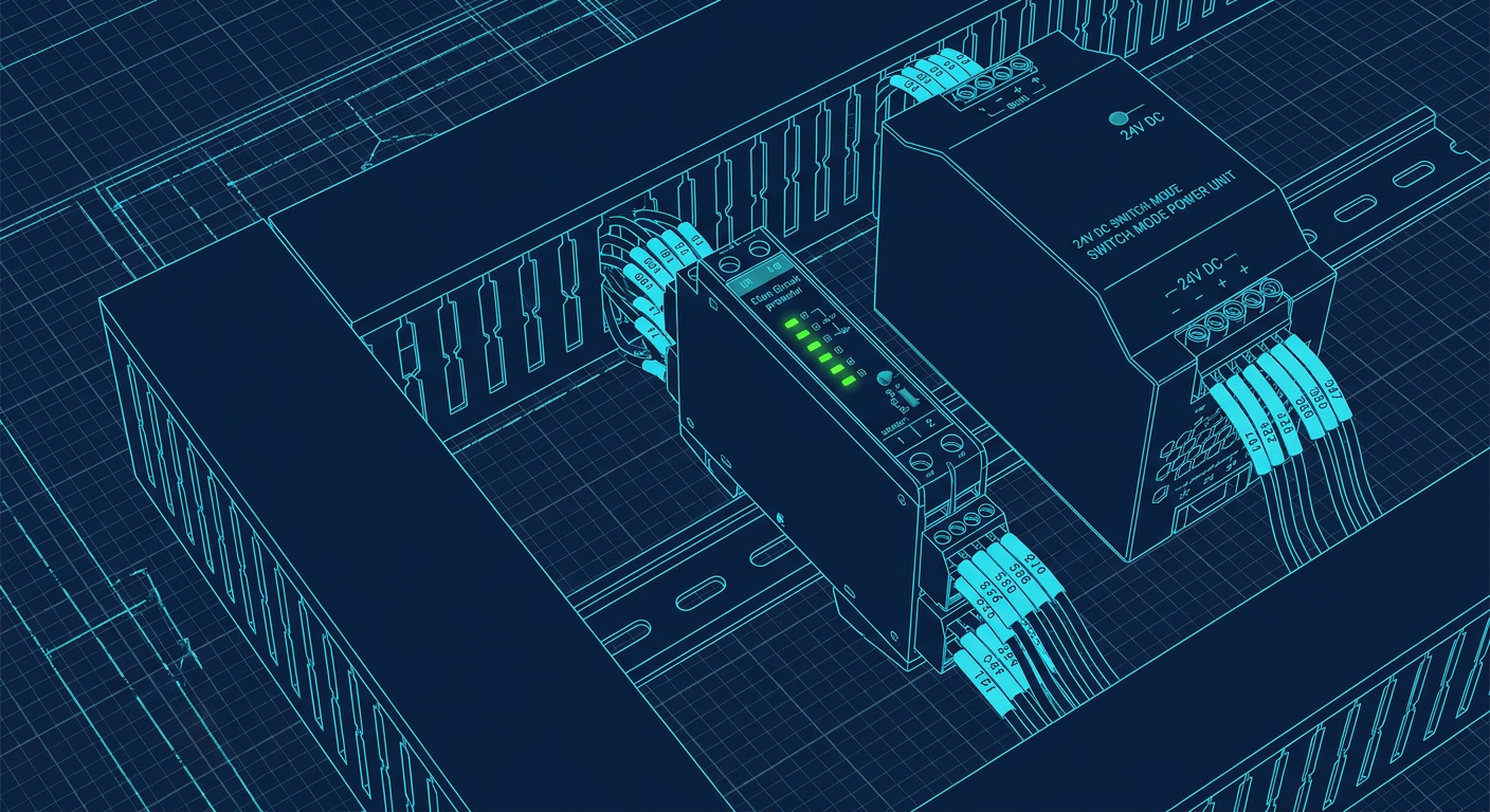
A field technician wires a 24V DC solenoid valve on a new pick-and-place cell. A stray strand of copper inside the valve connector bridges positive to negative, creating a dead short. In an ideal world, the miniature circuit breaker protecting that branch trips with a crisp click, the fault is isolated, and the rest of the machine keeps running.
In reality, the breaker lever does not move. It sits there, stubbornly closed, while the 24V power supply hums quietly, its green status LED flashing red. Across the entire control box, every indicator light dies. The PLC reboots, the managed Ethernet switch drops connection, the safety controller faults out, and the HMI goes blank.
Nothing burned, but the entire machine died because of a short on a single valve coil. If you have spent time around automated machinery or custom test benches, you have probably seen this happen. You might have assumed the breaker was defective, or that you needed a lower amp rating.
Neither assumption is right. The problem is a fundamental mismatch between how switch-mode power supplies handle overcurrent and how traditional thermal-magnetic breakers trip.
The Physics Behind the Failure
Most generalist engineers select miniature circuit breakers (MCBs) for 24V DC distribution because they are cheap, familiar, and easy to source from distributors like AutomationDirect, DigiKey, or RS Components. You pick a 2A or 4A C-curve breaker, snap it onto the DIN rail, and move on.
To understand why this fails, look at how a standard thermal-magnetic breaker works inside.
An MCB has two separate tripping mechanisms:
A bimetallic strip for thermal protection against sustained, low-level overloads. When current exceeds the rated current by 20 to 50 percent, the strip slowly heats up, bends, and releases the mechanical latch. This process takes anywhere from ten seconds to several minutes.
An electromagnetic coil for instantaneous short-circuit protection. When a massive surge of current rushes through the coil, the magnetic field yanks an armature forward to trip the latch in under 20 milliseconds, extinguishing the arc before wires melt.
The catch is the amount of current required to pull that magnetic armature. Circuit breakers are categorized by their instantaneous trip curves:
- B-curve breakers require 3 to 5 times their rated current to trip instantaneously.
- C-curve breakers require 5 to 10 times their rated current.
- D-curve breakers require 10 to 20 times their rated current.
Take a standard 4A C-curve breaker. To trip magnetically in 10 to 20 milliseconds, it needs between 20A and 40A of fault current. If you have a 6A C-curve breaker, it needs 30A to 60A.
Now look at your 24V DC power supply. Suppose you have a standard 10A, 240W DIN-rail switch-mode supply from Mean Well, PULS, or Phoenix Contact. A 10A power supply is electronically regulated. It cannot output 40A. Most modern industrial supplies have an overload limit of 110 to 150 percent of their rated output, meaning a 10A supply will max out at 11A to 15A before its internal protection circuitry intervenes.
When a short circuit occurs on your 4A branch, the circuit tries to pull huge current. The power supply immediately senses the overload and clamps down to protect its internal switching transistors. Depending on the supply design, it enters one of three states:
- Constant current mode: The supply limits the output current to roughly 110 percent of rating, causing the output voltage to collapse toward zero volts.
- Hiccup mode: The supply shuts down completely, waits a few hundred milliseconds, attempts to restart, hits the short again, and shuts down repeatedly.
- Foldback limiting: The supply drops both output voltage and current simultaneously.
In every case, the power supply output voltage drops from 24V down to under 5V in a few milliseconds.
Because the voltage collapsed, the maximum current flowing through the short circuit is capped at whatever the power supply delivers (say, 12A). That 12A is not enough to trip the magnetic coil of your 4A C-curve breaker (which needs 20A to 40A). The magnetic trip never engages.
The breaker is left waiting for its bimetallic strip to heat up. But at 12A split across the power supply or directly through a single 4A element, thermal tripping takes 5 to 30 seconds. While the bimetal strip is slowly warming up, the 24V rail is sitting near zero volts. The PLC CPU, which drops out when supply voltage falls below roughly 18V DC, dies instantly.
The Cable Impedance Trap
Even if you size your power supply with massive headroom (say, a 40A supply on a 4A branch), long field wiring often defeats magnetic tripping on 24V circuits.
Consider an automated assembly cell where a proximity sensor or push-button station is wired 25 meters away from the panel. The technician runs a standard 0.75 mm² (roughly 18 AWG) cable to the field device.
The loop resistance of 0.75 mm² copper wire is roughly 0.05 ohms per meter. A 25-meter run means 50 meters of total round-trip wire, which adds 2.5 ohms of resistance. Add 0.5 ohms of contact resistance across terminal blocks, connectors, and the fault itself, giving a total loop resistance of 3.0 ohms.
Apply Ohm's law to a direct short at the end of that cable:
$$\text{Current} = \frac{24\text{ V}}{3.0\ \Omega} = 8\text{ A}$$
No matter how large your power supply is, physics dictates that a 24V system cannot push more than 8A through that 3.0-ohm fault loop.
If that line is wired to a 2A C-curve breaker (magnetic trip threshold of 10A to 20A) or a 4A B-curve breaker (threshold of 12A to 20A), the magnetic trip will never see enough current to pop. The short circuit will draw 8A continuously. If you have an 8A or 10A supply, the supply will brown out, dragging the entire panel down with it, while the breaker stays firmly closed.
Why DC-Rated MCBs Do Not Fix This
Engineers sometimes realize that AC breakers behave poorly on DC, so they replace standard AC MCBs with specialized DC-rated miniature circuit breakers (such as Schneider Electric Acti9 iC60N DC or ABB S200M DC).
DC MCBs are essential when dealing with high-voltage DC circuits, like 400V solar string arrays or 125V battery banks, because DC arcs do not have a natural zero-crossing point and will destroy standard AC contacts. DC-rated breakers incorporate permanent magnets inside their arc chutes to blow the DC arc off the contact tips.
However, in a 24V DC control cabinet fed by a switch-mode power supply, DC-rated thermal-magnetic breakers still use the exact same bimetallic and magnetic coil operating principles. They still require 3x to 10x rated current for fast magnetic disconnection. Putting a DC-rated C-curve MCB in front of a switch-mode supply leaves you with the exact same failure mode.
How Electronic Circuit Protectors Work
Electronic Circuit Protectors (often abbreviated as ECPs or ECBs) replace the mechanical bimetal strip and magnetic coil with solid-state switching elements (MOSFETs) and high-speed current monitoring circuitry.
Inside an electronic protector, a precision shunt resistor or Hall-effect sensor measures current continuously. A microcontroller or dedicated analog ASIC monitors the current waveform.
When current exceeds the set threshold by even a small margin, the device reacts with calibrated electronic timing curves:
- Small overloads (e.g. 1.1 to 1.3 times the set current) are permitted for a few seconds to accommodate normal inrush, but will trip cleanly without requiring external heat.
- Moderate overloads (e.g. 1.5 to 2 times the set current) trip in roughly 100 milliseconds to 1 second.
- Hard short circuits trip in under 10 milliseconds, often in as little as 2 to 5 milliseconds.
Because the disconnection happens electronically via MOSFETs, the protector does not rely on raw fault current to generate mechanical force. An electronic protector set to 2A will disconnect a dead short in 5 milliseconds, even if the available short-circuit current is only 3A.
Active Current Limiting
The more capable class of electronic protectors includes active current limiting.
When a short circuit occurs, instead of letting current spike uncontrollably before shutting off, the internal MOSFET operates in its linear region for a few milliseconds, physically capping the maximum branch current to a fixed multiple (typically 1.25x to 1.7x of the set value).
If you have an electronic protector set to 4A with active current limiting capped at 1.3x, the fault current can never exceed 5.2A under any condition, even with zero loop resistance.
This completely changes the behavior of your power supply. The 24V DC supply barely registers a transient load change. The supply output voltage stays locked at 24.0V DC. The faulted channel shuts down cleanly, its local LED turns red, and the PLC, safety relays, HMIs, and every other branch circuit continue operating without a microsecond of brownout.
Handling Capacitive and Inductive Inrush
A common frustration with early solid-state fuses was nuisance tripping during normal switching events.
Industrial 24V devices create massive inrush spikes:
- Unmanaged field switches and remote IO slices have input filter capacitors that look like dead shorts for the first 500 microseconds of power-up.
- Solenoid valves and pneumatic manifold coils generate large inductive current peaks during pull-in.
- 24V DC motor brakes create significant switching noise.
If an electronic protector simply disconnected at a fixed current threshold without intelligent curve profiling, switching on a hydraulic proportional valve would trip the channel every time.
Modern electronic protectors handle this using programmed inrush curves. When an output channel turns on, the controller permits capacitive inrush currents of 20A or more for the first few milliseconds, provided the voltage profile indicates capacitor charging rather than a dead ground fault. Many multi-channel units also stagger their channel turn-on sequences by 50 to 100 milliseconds at startup. Instead of dumping the combined inrush of eight field branches onto your power supply at the same millisecond, the power supply sees a smooth, step-wise load ramp.
Hardware Options on the Market
Several industrial automation vendors produce dedicated 24V DC electronic circuit protectors. They fall into three architectural categories: modular backplane systems, fixed multi-channel blocks, and ultra-compact single-channel terminal blocks.
| Vendor | Product Family | Form Factor | Channels | Current Range per Channel | Key Feature |
|---|---|---|---|---|---|
| Phoenix Contact | CAPAROC | Modular plug-in | 1 to 4 per module (expandable) | 1A, 10A (adjustable or fixed) | Backplane power rails, IO-Link diagnostic interface |
| Phoenix Contact | PTCB | Single-channel slim block | 1 | 1A, 8A (adjustable) | 6.2 mm width, snaps into standard terminal block rows |
| Weidmüller | maxGUARD | Integrated distribution blocks | Modular single-channel slices | 0.5A, 16A | Combines electronic fuse with 0V and 24V distribution terminals |
| WAGO | 787 Series (EPSITRON) | Fixed block | 4 or 8 | 0.5A, 10A (switch selectable) | Compact footprint, digital input for remote reset |
| PULS | PISA-B / PISA11 | Fixed DIN block | 4 or 8 | 0.5A, 12A | Current-balancing protection, input voltage monitoring |
| Rockwell Automation | 1694 Series | Modular slices | 1, 2, or 4 | 0.5A, 10A | Direct integration with Allen-Bradley Point I/O architectures |
| Eaton | PXS24 | Modular slices | 1 per slice | 0.5A, 16A | Push-in terminals, sequential switching control |
Phoenix Contact CAPAROC and PTCB
Phoenix Contact offers two distinct approaches. For high channel counts with rich diagnostics, CAPAROC is a modular system. You install a central power feed module that feeds an internal copper backplane rail, then snap on 1-channel, 2-channel, or 4-channel protection slices without running external jumper bars. CAPAROC modules support IO-Link, allowing a PLC to read real-time branch current, log transient spikes, and adjust trip thresholds in software.
For compact panels or retrofits, the PTCB series is 6.2 millimeters wide per channel. It matches the profile of standard terminal blocks, making it straightforward to replace standard glass fuses or single-pole breakers without redesigning panel layouts.
Weidmüller maxGUARD
In standard control panels, wiring a circuit breaker requires three elements: the breaker itself, a terminal block to distribute the positive 24V field wire, and a terminal block for the 0V common return wire. This takes up substantial DIN rail length.
Weidmüller's maxGUARD integrates the electronic disconnect, the 24V distribution terminal, and the common 0V return distribution terminal into a single continuous slice. Cross-connection jumpers link the positive and negative buses across the entire bank internally. This architecture cuts cabinet wiring time significantly and eliminates external potential distribution blocks.
WAGO 787 Series
WAGO makes fixed 4-channel and 8-channel compact units. They feature rotary dials or push-buttons on the front face to set the current limit per channel (for example, in 1A increments from 1A to 10A). They do not require software or programming tools to commission. WAGO units include a common alarm relay contact and a 24V digital input terminal that allows a PLC digital output to reset tripped channels remotely after a fault is cleared.
PULS PISA
PULS approaches 24V distribution from the perspective of power supply protection. Their PISA modules continuously monitor the input voltage rail coming from the main supply. If the 24V rail drops below 21V for any reason, PISA instantly sheds lower-priority output branches to protect critical loads (like PLCs and safety controllers) before the power supply collapses into hiccup mode.
Practical Design and Wiring Rules
When designing a 24V distribution layout with electronic circuit protectors, a few practical rules prevent headaches during field commissioning.
1. Separate Control Power from Actuator Power
Never put sensitive control electronics on the same protection channel as field actuators. A standard best-practice layout uses at least four distinct branches:
- Branch 1 (PLC & Logic): PLC main rack, Ethernet switches, remote IO bus couplers. Set low (typically 2A to 4A).
- Branch 2 (Safety Devices): Safety relays, light curtains, emergency stop monitoring circuits, safety interlocks. Set to 2A or 4A.
- Branch 3 (Sensors & Inputs): Field proximity sensors, photoeyes, digital input power. If an operator pinches a cable on a conveyor, only the sensor power trips while the PLC stays alive and reports the exact diagnostic error on the HMI.
- Branch 4 (Actuators & Outputs): Solenoid valves, relay coils, indicator lamps. This branch experiences the highest electrical noise and physical risk.
When using tools like LabCD to lay out panel schematics and synthesize wiring schedules, defining these branch functional groups early ensures that power architecture and fuse channel sizing automatically align with device categories.
2. Manage the 0V Common Return
One of the most common panel build mistakes is focusing entirely on the +24V rail while ignoring the 0V return wiring.
Every ampere of current leaving the +24V supply must return to the 0V terminal. If you run four 4A branches out through an electronic protector but return all field common lines through a single undersized 0.75 mm² wire back to the power supply, that return wire becomes a massive resistive bottleneck. It will induce ground offsets, cause analog sensor drift, and increase total loop impedance during short circuits.
Always ensure your 0V distribution busbar or multi-tier terminal block row matches or exceeds the cross-sectional copper area of your main positive supply conductors. Systems like Weidmüller maxGUARD solve this by providing dedicated 0V terminals on each slice with internal heavy-gauge cross-connection bars.
3. Wire Sizing and Branch Setting Rules
Under UL 508A and IEC 60204-1 panel standards, circuit protection must protect the smallest conductor wired downstream.
If you set an electronic circuit protector channel to 6A, every piece of wire on that branch (including field device pig-tails) must be sized to safely carry continuous overload current without overheating before the channel trips.
As a practical rule for 24V DC panel wiring:
- 0.5 mm² (20 AWG): Max setting 3A to 4A
- 0.75 mm² (18 AWG): Max setting 4A to 6A
- 1.5 mm² (16 AWG): Max setting 8A to 10A
- 2.5 mm² (14 AWG): Max setting 10A to 16A
Using electronic protectors with dial-selectable current settings makes this easy. If a specific sensor circuit uses thin 0.34 mm² (22 AWG) cable, turn the rotary dial on that channel down to 1A or 2A.
4. Wire Remote Reset and Alarm Signaling
Do not leave the alarm contacts on your electronic protectors floating. Every major protector provides either a dry relay contact or a transistor status output.
Wire the collective fault output to a digital input on your PLC. In your logic, latch an alarm that displays on the HMI: 24V DC Branch Fault - Check Channel 3 (Field Sensors).
If the protector supports remote reset, wire a spare PLC digital output to the reset terminal. This allows an operator or remote technician to reset a tripped channel from the HMI screen after clearing a jam or replacing a damaged sensor, without requiring a maintenance electrician to put on arc-flash PPE, unlock the enclosure, and manually press buttons inside the live panel.
What to Check in Your Next Panel
If you are reviewing an existing machine build or finalizing schematics for a new control box, take ten minutes to audit the 24V power architecture:
- Check the secondary side of your 24V power supply. If you see standard 1-pole AC MCBs with C-curve markings, calculate the magnetic trip threshold ($5 \times I_n$). If that number exceeds 120 percent of your power supply rating, those breakers will not provide fast short-circuit protection.
- Verify branch isolation. Ensure your PLC CPU and communications hardware are not sharing a circuit with inductive solenoid valves or external field plugs that can be crushed by forklifts or tooling.
- Verify wire loop lengths. If any field sensor or push-button box is more than 15 meters away, check whether the cable loop resistance limits short-circuit current below the trip point of your chosen fuse.
Switching to multi-channel electronic circuit protectors costs slightly more in raw component hardware than bottom-tier MCBs, typically an extra $15 to $25 per protected channel. But it eliminates nuisance supply collapse, protects wiring down to thin gauge limits, and cuts hours of troubleshooting when a single field device develops a dead short on the plant floor.
Sources
- https://www.eaton.com/content/dam/eaton/markets/machinebuilding/protect-personnel-assets-and-machine-reliability/documents/documents-english-language/eaton-control-overcurrents-safety-pxs24-whitepaper-wp012021-en.pdf
- https://www.pulspower.com/cam/blog/mcb-vs-efuse-which-is-the-best-solution-for-properly-securing-dc-circuits/
- https://www.rockwellautomation.com/en-us/products/hardware/circuit-and-load-protection.html
- https://www.reddit.com/r/PLC/comments/1prkwe9/protecting_low_power_24v_dc_devices/