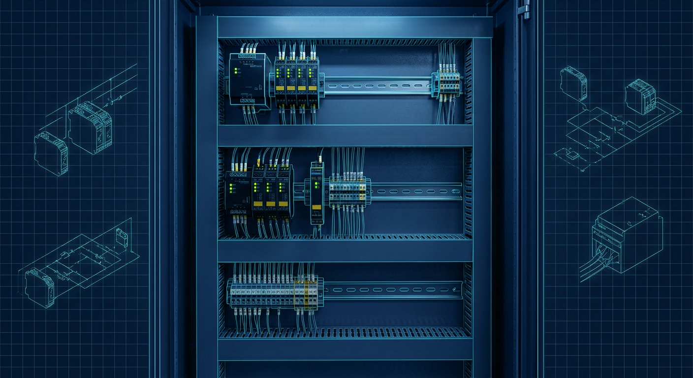
You just finished designing the mechanical frame for a small automated assembly cell. The cell has two emergency stop pushbuttons, one optical safety light curtain at the load station, an interlocked safety switch on the rear access door, and two force-guided contactors that drop 3-phase power to a pair of motor drives.
Now you have to order the safety hardware for the control box.
If control panels are not your daily trade, your initial instinct is usually to grab a few discrete safety relays from the catalog. You pick an E-stop relay for the pushbuttons, an optical interface relay for the light curtain, and another dual-channel relay for the door switch. Each relay costs roughly $130 to $220. The total hardware bill looks like $500.
A compact configurable safety controller from Banner, Sick, Keyence, or Pilz costs between $650 and $950. At first glance on a purchase order, the safety relays look like the cheaper, simpler choice. No programming software to download, no USB cables to hunt down, and no firmware to patch.
That calculation is wrong on almost every small cell with more than two safety devices. Once you account for inter-relay wiring, pulse testing, external device monitoring (EDM), panel width, and the time spent hunting down a cross-fault with a multimeter, hardwired safety relays stop being cheap the moment you wire the third unit.
Here is how the math actually breaks down, where the break-even line sits, and how to avoid building a wiring rat's nest in your next control box.
The Real Cost of Discrete Safety Relays
A basic safety relay is a dedicated, hardware-level logic module. Inside, it uses force-guided mechanical relays or solid-state outputs arranged with internal cross-checking. If one internal contact welds shut, the module detects the fault and prevents restarting.
For a single standalone machine with one E-stop button and a reset button, a dedicated safety relay is unbeatable. You buy one unit (like a Phoenix Contact PSR or an Omron G9SA), snap it onto a 22.5 mm DIN rail slice, run four wires to the button, two wires to the reset switch, and wire the output contacts in series with your main contactor coils. You are done in thirty minutes.
The trouble starts when your safety architecture needs multiple inputs to interact.
Consider what happens when you have three independent safety inputs:
- Two dual-channel E-stops wired in series.
- One Type 4 safety light curtain with PNP OSSD (Output Signal Switching Device) outputs.
- One dual-channel RFID tongue interlock switch on the maintenance door.
In a standard Category 4 / Performance Level e (PL e) architecture, these three inputs cannot simply be daisy-chained into one generic relay if you want individual fault detection and clear status indication. You need three separate safety relays.
To make the machine safe, all three relays must be able to shut down the cell. That means you must wire the safe output contacts of Relay 1 into the power or enable circuit of Relay 2, or wire all three safe outputs in series to drive the master control relays.
Suddenly, your bill of materials is not just three relays. You need:
- Three 22.5 mm or 45 mm DIN rail modules taking up 70 to 135 mm of panel width.
- Jumper wires jumping safe outputs between relays.
- Feedback loops (EDM) wired through the auxiliary contacts of both main contactors back to the reset circuit of every single relay, or through a master reset relay.
- Separate auxiliary signal wires running from each relay back to your standard machine PLC so the HMI can show which device tripped.
By the time you finish stripping, ferrule-crimping, labeling, and landing those conductors, you have routed between 28 and 42 individual control wires inside wire duct that is now completely full.
The Hidden Assembly and Debug Labor
If you assemble your own control boxes or manage technicians who build them, the hidden expense of hardwired safety relays is assembly time and continuity testing.
Every dual-channel safety device requires two independent input circuits (Channel A and Channel B). For mechanical switches, the relay generates test pulses (usually marked S11/S21 or T1/T2) that cycle high and low at microsecond intervals. If Channel A shorts to Channel B, or if a wire pinches against the grounded machine frame, the relay detects the pulse mismatch and locks out.
Wiring this with discrete hardware means:
- Running two test pulse lines out to the switch.
- Running two return signal lines back to the relay terminals.
- Wiring the reset circuit with button illumination.
- Wiring dual normally closed auxiliary contacts from your contactors back into the feedback loop.
If a technician accidentally swaps the test pulse lines on the terminal block, the safety relay goes into a fault state. The only diagnostic feedback on the relay faceplate is a red light or a blinking pattern. You now have to open the schematic, grab a multimeter, and probe terminal by terminal while flipping the switch to figure out which channel is inverted.
At typical industrial shop rates ($75 to $125 per hour for electrical panel assembly and checkout), spending an extra three hours wiring and troubleshooting a multi-relay chain wipes out any hardware savings before the panel ever ships out the door.
What a Compact Safety Controller Actually Does
A compact safety controller is not a massive, expensive safety PLC like an Allen-Bradley GuardLogix or a Siemens S7-1500F. Those modular systems are built for entire production lines and start at several thousand dollars.
Compact configurable safety controllers (such as the Banner SC10 / XS26 series, Keyence SC / GS series, Sick Flexi Compact, or Pilz PNOZmulti mini) are self-contained, base units specifically designed to replace three to eight discrete safety relays. They typically cost between $650 and $1,100, occupy 45 mm to 67 mm of DIN rail space, and feature:
- 8 to 26 safe inputs (configurable for dual-channel dry contacts, OSSD solid-state signals, two-hand controls, or muting sensors).
- 2 to 4 independent dual-channel safe solid-state or relay outputs.
- Built-in test pulse generators assigned via software.
- Onboard industrial Ethernet (EtherNet/IP, Modbus TCP, or Profinet) or a digital status bus.
Instead of running jumper wires between relays to build logic, you plug a standard USB or micro-USB cable into the front of the unit and draw the logic on a free PC configuration utility. An E-stop block, a light curtain block, and an interlock block connect directly to an AND gate, which drives your safe outputs.
[E-Stop 1 & 2] ----+
[Light Curtain] ---+---> [ AND GATE ] ---> [Off-Delay Timer] ---> [Safe Outputs: K1/K2]
[Interlock Door] --+
                          ^
[Reset Button] -----------+
[EDM Feedback] -----------+
Because the logic is internal, all inter-device wiring disappears. You land the field wires directly on the controller spring terminals once. There are no cascading jumpers, no interposing signal relays, and no auxiliary contact wiring to feed status back to the main PLC.
The Clear Break-Even Point: The Rule of Three
Over hundreds of small robotic cells, standalone test benches, and packaging stations, the crossover point between discrete safety relays and configurable safety controllers is remarkably consistent.
The 1 to 2 Device Range: Hardwired Relays Win
If your machine has only an E-stop button and one perimeter interlock, use one or two discrete safety relays. The hardware cost is low ($250 to $350 total), wiring is straightforward, and introducing a software configuration step offers little practical benefit. It is easy to document and requires no software licenses or backup project files for the maintenance team.
The 3-Device Mark: The Dead Zone
At exactly three devices (for example: two E-stops, one light curtain, one interlocked latch), the direct hardware cost of discrete relays is roughly $500 versus $750 for a compact controller. However, the controller saves approximately two to three hours of panel build and test time, uses roughly half the DIN rail real estate, and eliminates eight to twelve terminal blocks. At this threshold, the total installed cost is identical.
The 4+ Device Range: Configurable Controllers Win Decisively
The moment you have four or more safety functions (for example: an E-stop, a light curtain, an access door, a foot switch, and an area scanner), discrete safety relays become an engineering mistake. Four discrete relays cost nearly the same as a base configurable controller, take up massive panel space, and introduce an unmanageable web of series-wired contacts and feedback loops.
| Feature | 4 Discrete Safety Relays | 1 Compact Safety Controller (e.g. Banner SC10 / Sick Flexi) |
|---|---|---|
| Hardware Cost | $600 to $900 | $650 to $950 |
| DIN Rail Width | 90 mm to 180 mm | 45 mm to 67 mm |
| Field Terminations | 32 to 48 wire points | 16 to 24 wire points |
| Inter-Relay Logic Wiring | 10 to 16 jumper wires | 0 (configured in software) |
| PLC Diagnostic Points | Requires 4 auxiliary inputs | Transmitted over Ethernet or single comms line |
| Audit Documentation | Manual wiring tracing + SISTEMA | Exportable automated validation report |
| Modification Time | Rewire terminals, add relays | Edit logic block in software, download |
Real-World Troubleshooting at 2:00 AM
The most convincing argument for a configurable controller is what happens when a machine stops on the production floor.
Imagine a machine operator pushes an E-stop, pulls it back out, and presses the blue reset button. Nothing happens. The main contactors will not pull in.
If you built the panel with discrete safety relays, here is what the technician has to do:
- Open the high-voltage electrical enclosure doors while following arc flash protocols.
- Look at six tiny green LEDs across three separate plastic housings.
- Notice that Relay 2 has an 'In 1' LED on, but 'In 2' is off.
- Pull out the electrical prints to find what 'In 2' on Relay 2 connects to.
- Discover it goes to Channel B of the door interlock switch on the other side of the machine.
- Trace the cable through the cable drag chain with a multimeter to find a broken conductor.
If you built the panel with a configurable controller connected to your machine PLC over basic industrial Ethernet or Modbus TCP, the technician never opens the cabinet door.
The safety controller continuously broadcasts the status of every input, output, and internal logic block. The cell HMI instantly displays: "Safety Interlock Door 1: Channel B Open Circuit Fault - Check Cable or Switch Contact 2."
Even on simple cells without a main PLC or HMI, configurable controllers like the Banner SC10 or Keyence SC have multi-segment displays or multi-color LEDs on the front faceplate. Instead of a solid green light, the controller flashes an explicit error code indicating that the EDM feedback loop did not close within the 200 ms timeout window. You know immediately that a main contactor contact is sticking, without touching a meter probe.
Audits, CE Marking, and ISO 13849-1 Validation
If your equipment requires formal risk assessment validation, CE marking, or an OSHA/ANSI compliance review, you must prove your safety circuit meets a required Performance Level (typically PL r = d or e) under ISO 13849-1.
Validating hardwired relays in calculation software like SISTEMA requires tedious data entry. You must create safety functions for each branch, enter the MTTF_d (Mean Time to Dangerous Failure) values for each relay, calculate the DC_avg (Diagnostic Coverage) based on your series wiring methods, and evaluate common cause failures (CCF) across your inter-relay wiring.
When you wire safe contacts in series (for example, chaining the auxiliary outputs of multiple door switches across safety relays), you introduce fault masking. Fault masking occurs when a fault on one switch is hidden because another switch opens before the relay can detect the discrepancy. Under ISO 13849-1, fault masking severely penalizes your Diagnostic Coverage score, often dropping a system designed for PL e down to PL d or PL c.
Configurable controllers eliminate fault masking entirely because every field device lands on its own dedicated dual-channel input slice. The controller independently monitors each input and executes test pulse validation at all times.
When it comes time to produce the audit binder, the software utility for the safety controller generates a complete verification report with one click. It prints out the checksum of the running safety program, the wiring pinout, the configured input types, the response times, and the achieved SIL / PL rating. You print the PDF, sign it, and place it in the machine technical file. During a safety audit, handing an inspector a generated validation sheet with a matching software checksum is much cleaner than asking them to trace jumper wires across terminal strips.
Physical Panel Space and Layout
Control panel enclosures for small automated cells are getting smaller. When you are retrofitting a safety circuit onto an existing machine or building a compact cart-mounted workstation, DIN rail real estate is precious.
Four discrete safety relays side-by-side consume at least 90 mm of horizontal DIN rail width. But the space penalty is actually worse than that. Because discrete relays require top and bottom wiring for input loops, reset circuits, power, and outputs, you need deep wire ducts above and below them. The total vertical and horizontal footprint can easily eat up a 200 mm by 200 mm quadrant of your backplate.
A single compact configurable controller requires 45 mm to 67 mm of DIN rail space. Because you land all inputs on one unit, your external field wiring routes directly into a single set of terminal blocks.
When planning control box layouts in tools like LabCD, laying out a single configurable controller reduces the required clearance around wire duct channels, simplifies internal power distribution buses, and avoids the messy cross-duct wire runs that make panels difficult to service.
Practical Rules for Wiring Your First Configurable Unit
If you decide to switch from discrete relays to a configurable safety controller, keep these practical wiring rules in mind during design:
1. Separate Dry Contact Test Pulses from OSSD Inputs
Do not use safety controller test pulse outputs (T1/T2) on solid-state devices. Electronic safety sensors (like optical light curtains, laser scanners, or RFID switches with active internal circuits) generate their own internal OSSD test pulses. In your controller configuration software, you must configure those inputs as "OSSD Inputs" or "Solid-State Inputs" rather than "Dry Contact Dual Channel". If you connect controller test pulses to an active OSSD device, the two pulse generators will conflict and cause nuisance tripping.
2. Isolate Your External Device Monitoring (EDM)
Do not route contactor feedback contacts into standard machine PLC inputs if you want PL e compliance. Route the normally closed auxiliary contacts of your safe switching devices (force-guided contactors, safe torque off feedback pins, or pneumatic dump valves) directly into a dedicated EDM input on the safety controller. Configure the controller with a 200 ms to 300 ms debounce window to prevent nuisance faults during normal mechanical contactor pull-in.
3. Choose the Right Output Type for the Load
Safety controllers come with two types of safe outputs: solid-state PNP outputs and force-guided relay outputs.
- PNP Solid-State Outputs: Best for driving Safe Torque Off (STO) inputs on modern servo drives and variable frequency drives. They switch instantly, do not suffer from mechanical contact wear, and can perform automatic pulse testing.
- Dry Relay Outputs: Necessary if you are cutting 120V AC control power, switching heavy 24V DC contactor coils that pull several amps of inrush current, or integrating with an older third-party machine interface that requires dry, volt-free contact closure.
If your controller only has solid-state PNP outputs and you need to drop power to a heavy contactor coil, order a matching slim safety relay expansion module (such as a 12 mm or 17.5 mm contact output block) that plugs directly into the controller bus or connects to the PNP output with EDM feedback.
What to Do on Your Next Build
Before you start laying out your next control box schematic or ordering parts from your distributor, count your safety inputs.
If you have one E-stop and one safety gate: stick with a single or dual discrete safety relay. Keep it simple and skip the configuration software.
If you have three or more safety devices, or if you need to pass safety diagnostic data over Ethernet to an operator screen: skip the discrete relays entirely. Select a compact base unit from Banner (SC10 or XS26), Sick (Flexi Compact), Keyence (SC1000), or Pilz (PNOZmulti mini).
Check the configuration software before you buy. Most vendors offer their safety logic configurator as a free download without requiring paid engineering licenses. Spend fifteen minutes creating your logic offline. Once you see your safety circuit laid out with drag-and-drop functional blocks, clear input pin assignments, and zero cascading jumper wires, you will never want to hardwire a chain of safety relays again.
Sources
- https://forum.digikey.com/t/safety-relay-or-safety-plc-a-system-level-comparison/67835
- https://www.controldesign.com/safety/safety-components/article/11338888/machine-safety-safety-relay-or-safety-rated-plc
- https://www.plctalk.net/forums/threads/compact-guardlogix-vs-safety-relays.122866/
- https://industrialmonitordirect.com/blogs/knowledgebase/compact-guardlogix-vs-safety-relay-selection-criteria?srsltid=AU7gw4WLK1cx-J1O5VM4aniDloaJmu4v-NfwGh73zeum_St2CSmDxruG