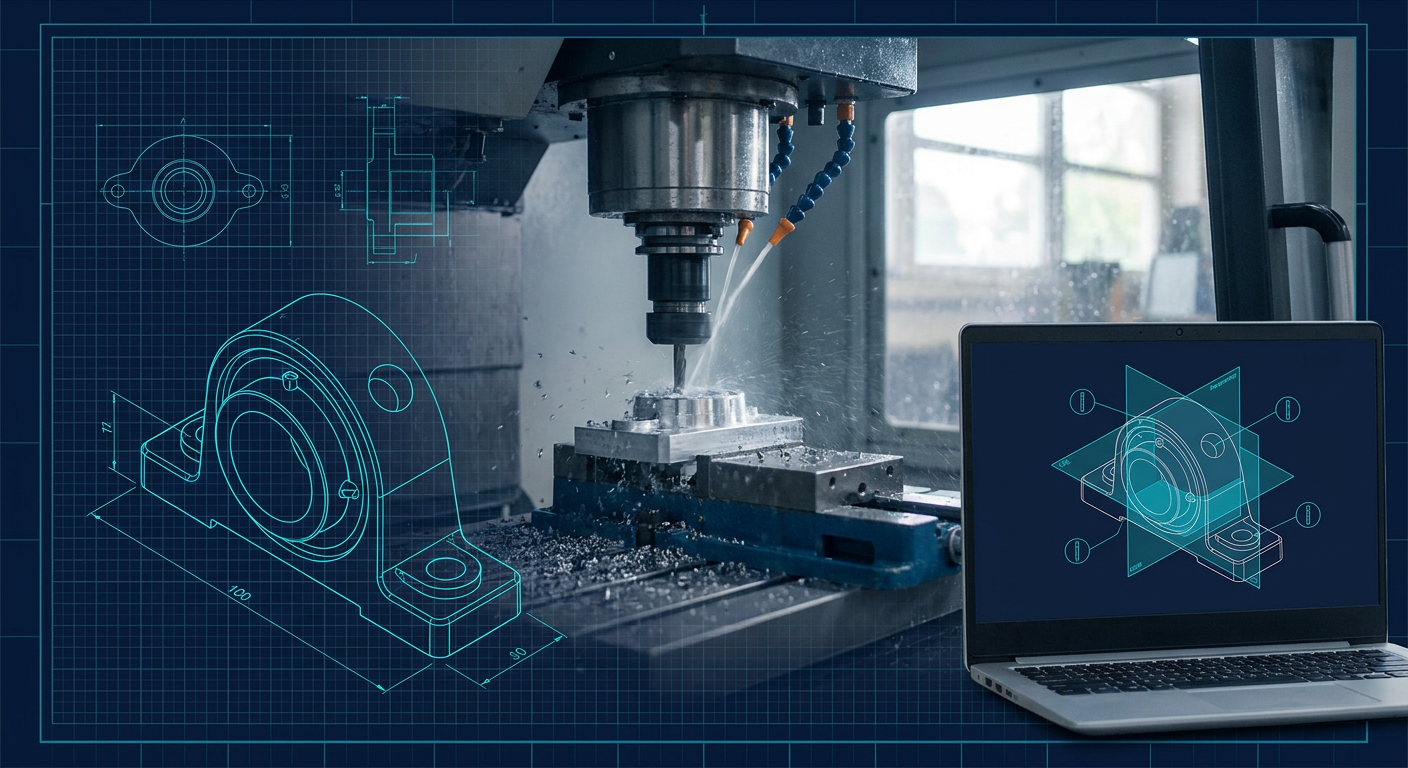
Drop an AI-generated 3D bracket into your CAM software, hit post-processor, and watch your shop manager walk over to your desk. If that file was generated by a diffusion mesh model and saved out as an STL, you gave him a bag of triangles.
Triangles do not have centerlines. They do not have analytical axes. They do not have pitch diameters, thread relief grooves, or cylindrical surfaces that your CAM package can pick up for a helical boring cycle.
Over the last eighteen months, the internet has filled with videos showing natural language prompts turning into rotating 3D models in five seconds. Type in a prompt for a motor mount, get a 3D asset. But there is a massive gulf between a visual 3D asset and a machining file. If you run a vertical machining centre or an automated lathe cell, an STL or a tessellated polygon hull is almost useless. To cut metal without scrapping 6061 bar stock or breaking 3mm carbide end mills, you need Boundary Representation (B-Rep) geometry saved in a neutral file format like STEP AP214 or AP242. You need clean sketch planes, true arcs, and explicit datums.
We spent the past month testing the current crop of text-to-CAD engines, including Zoo.dev, Leo AI, and various script-driven LLM pipelines, to see if any of them can produce a part that an actual machinist can make.
The Shop Floor Failure Mode: Meshes vs Analytical Geometry
To understand why text-to-mesh tools fail on the shop floor, look at what happens inside a CNC control unit when it reads toolpaths.
When CAM software encounters a true B-Rep cylinder, it reads an exact mathematical definition: a radius $R$ swept along a vector between two planar bounds. When you generate a toolpath for that hole, the CAM software outputs circular interpolation commands, typically G02 and G03. The machine controller receives an arc center and a sweep angle. It accelerates the X and Y axes smoothly through a continuous curve, maintaining constant chipload on the flute.
When you import a mesh, even one exported as a fake STEP file via surface-stitching plugins, that cylinder becomes a prism built from two hundred flat facets.
Traditional B-Rep Cylinder:     G02 X25.0 Y0.0 I-25.0 J0.0 F450.

Mesh Surface Approximation:     G01 X24.98 Y0.87 F450.
                                G01 X24.91 Y1.74 F450.
                                G01 X24.80 Y2.61 F450.
                                [... 400 lines of point-to-point feed]
Feed those 400 lines into an older Haas or Fanuc controller with limited lookahead memory. The machine chokes on the buffer. Feed rate drops, the tool chatters in the cut, and you end up with chordal error flats all over the bore. If that bore was meant for a 608 bearing with an H7 slip fit (+0.012 mm / -0.000 mm), your bearing will either sit loose on the high spots or rock on the polygon ridges.
There is no way to salvage this in CAM without manually redrawing the hole. You cannot select the cylinder axis for a canned drilling cycle (G81/G83) because the mesh does not have an axis. You cannot probe the top face with a Renishaw probe because there is no single plane, only a fragmented mosaic of microscopic faces.
The Three Approaches to Text-to-CAD
Recent tools attempting to solve this problem fall into three distinct technical buckets. Each handles geometry generation differently, and only two of them are relevant to mechanical design.
1. Direct Neural Mesh Generation
These tools run text prompts through diffusion networks trained on 3D computer graphics assets (like ShapeNet or Objaverse). They output signed distance functions (SDFs) or voxels that convert into polygon meshes (OBJ, STL, USDZ).
They are built for video game prop artists and concept sculptors. They do not understand that a counterbore needs to be concentric with a through-hole. When you ask for a flange with four M6 bolt holes on an 80mm bolt circle, you get four irregular, slightly oval depressions spaced roughly 90 degrees apart, none of which will line up with a standard mating pattern. These tools have zero place in a machining environment.
2. Code-Generation via Programmatic CAD
This approach uses large language models to write code targeting programmatic CAD kernels such as OpenSCAD, CadQuery (built on OpenCASCADE), or proprietary DSLs like Zoo's KittyCAD Design Language (KCL).
User Prompt -> LLM Reasoning -> Python/CadQuery Script -> OpenCASCADE Kernel -> Real STEP / B-Rep
The LLM never touches geometry directly. Instead, it writes code that calls boolean primitives, sketch extrusions, chamfers, and fillets within a deterministic geometry engine. Because the engine itself enforces mathematical constraints, the resulting export is a real STEP file with true cylindrical faces, planar datums, and sharp edges.
3. API-Driven Parametric Modellers
Platforms like Leo AI focus on turning prompts into structured CAD operations executed within traditional commercial CAD software environments or dedicated parametric constraint solvers. Instead of spitting out static geometry, they generate sketch relationships, dimensions, and feature trees. You end up with sketches containing coincidence, tangency, and perpendicularity constraints, followed by parametric extrudes and cuts.
Benchmarking on Real Machine Shop Test Parts
To test these systems, we avoided vague prompts like "make a cool robot arm." We used three common machine shop tasks that every junior designer has to draft weekly.
Test 1: NEMA 23 Stepper Motor Mount Plate
Requirements: 6061-T6 aluminium plate, 8mm thick. 38.1mm pilot register bore (tolerance +0.03/-0.00). Four 5.2mm clearance holes on a 47.14mm square bolt pattern. Two slotted mounting feet at the base for M5 fasteners.
- Zoo.dev (KCL pipeline): Generated a clean, fully manifold solid. The pilot bore was an exact analytical cylinder. The four mounting holes were correctly positioned on a 47.14mm bolt circle using mathematical variables. When imported into Autodesk Fusion, the CAM module instantly recognized the holes for a standard drilling operation. However, the slot radiuses at the base lacked tangency constraints in the sketch code, resulting in tiny 0.05mm steps where the slot arcs met the straight lines.
- CadQuery Code Scripting (via standard LLM agents): When prompted with precise engineering coordinates, an agent writing CadQuery produced a flawless STEP file. The code explicitly set the pilot bore diameter to 38.1mm and used a polar array for the bolt holes. The entire model was editable in four lines of Python. The failure occurred when we did not explicitly give it the bolt circle diameter: the LLM guessed 50.0mm instead of looking up the NEMA 23 standard specification.
- Mesh-to-STEP Converters: Utter failure. The pilot bore was segmented into 128 facets. Standard hole recognition failed completely in Mastercam.
| Feature Requirement | Mesh-First AI Output | Script-Based B-Rep (Zoo / CadQuery) | Traditional CAD Manual Draft |
|---|---|---|---|
| File Geometry | Polygon Mesh / Facets | Exact B-Rep Solid | Exact B-Rep Solid |
| Hole Recognition in CAM | Fails (Manual 3D path needed) | Passes (Automatic G81/G83 cycles) | Passes (Automatic G81/G83 cycles) |
| Dimensional Fidelity | Drifts +/- 0.5mm to 1.5mm | Exact to prompt dimensions | Exact to drawing specifications |
| Centerline Extraction | Impossible without rebuild | Instant (Cylindrical entity) | Instant (Cylindrical entity) |
| Editability | Non-parametric (Mesh sculping) | High (Modify script variables) | High (Modify feature tree) |
Test 2: Double-Bearing Pillow Block for a 20mm Linear Shaft
Requirements: 6082 aluminium housing. Two bores for 6004 bearings (42mm outer diameter, 12mm width). Central grease groove. Two M8 tapped holes for mounting to an aluminium extrusion base.
This test exposed the limits of current AI CAD tools.
None of the automated text-to-CAD tools managed to model the internal circlip retention grooves or the grease fitting passage correctly. When Zoo.dev and Leo AI built the main bore, they extruded a single through-hole. When prompted to add internal steps for the bearing shoulders, the engines frequently broke their boolean operations, producing self-intersecting loops or failing kernel operations in OpenCASCADE.
Text prompts struggle to communicate complex internal topological relationships without dense engineering terminology. To get the bearing shoulders right, we had to write a prompt that read like a complete G-code program, specifying inner shoulder diameters, wall offsets, and chamfer depths. At that point, typing the prompt took longer than sketching the profile and revolving it manually in SolidWorks.
Test 3: Thin-Walled Electronics Enclosure with M3 Brass Heat-Set Bosses
Requirements: Polycarbonate enclosure, 2mm nominal wall thickness. Four interior standoff bosses (6.0mm OD, 4.0mm blind hole, 5mm depth) spaced to match an Arduino Uno mounting footprint. Lip-and-groove perimeter seal.
- Zoo.dev: Successfully created the thin-walled shell using an offset/shell operation, but failed to ground the standoff bosses to the internal floor. The bosses floated 0.2mm above the bottom face because the extrusion plane was set to the top lip rather than the internal cavity floor.
- Code-Generation Pipelines: Handled the standoff locations well when supplied with explicit hole coordinates. However, creating the perimeter lip-and-groove joint caused the geometry kernel to throw an invalid topological manifold error. Complex sweeps along 3D profile edges remain a major weak spot for programmatic text-to-CAD generators.
The Real Gap: Datums, Tolerancing, and GD&T
Even when an AI tool produces a clean STEP file, it leaves out the information that machine shops actually use to make parts: tolerances, datums, and surface finishes.
A STEP file contains nominal geometry. It says a hole is 20.000000mm in diameter. But in the physical world, there is no such thing as a 20.000000mm hole. It is either 20.015mm or 19.985mm depending on tool wear, spindle runout, thermal expansion, and feed rate.
Nominal Model (What AI outputs):   D = 20.000 mm
Machinist Drawing (What CAM needs): D = 20.000 mm +0.021/+0.008 (H7 Press Fit)
                                   Datum A (Base): Parallelism within 0.02mm
                                   Surface Finish: Ra 0.8 on bearing seats
When an engineer draws a part, they design around a Datum Reference Frame. They select Datum A (the mounting face), Datum B (the locating pin), and Datum C (the anti-rotation edge). Tool paths, fixture setups, and CMM inspection routines are built entirely around these datums.
Current text-to-CAD tools do not think in datum reference frames. They place parts arbitrarily in global coordinate space. A bracket might have its origin floating in empty space 40mm behind the part, with the primary mounting plane tilted 0.3 degrees relative to the XY plane.
Before you can cut that part, an NC programmer has to open the file, re-align the body to the machine coordinate system (MCS), establish the work coordinate system (WCS / G54), and verify that the mating planes are truly flat rather than slightly skewed by an unconstrained generative algorithm.
Where Mechanically-Sound AI CAD Actually Works
AI CAD becomes genuinely productive when you stop asking it to be an artist and start using it as an automated scriptwriter inside a rigid geometric environment.
Tools that let engineers write and inspect code (like KCL in Zoo.dev, or Python in CadQuery) allow you to parameterize your shop standards. You can build a library of standardized prompt templates for your specific tooling and machine capabilities.
For example, if your shop uses specific thread relief dimensions, cutter radiuses, and standard stock thicknesses (such as 6.35mm or 12.7mm plate), you can constrain the system to only pick dimensions from your raw material rack.
At IDO, our mechanical generative systems under Mexaio AI approach this by strictly separating the reasoning layer from the geometric kernel. The language model handles functional constraints and component positioning, but delegates all geometry creation to an exact parametric solver that enforces closed sketch loops, tangency, and standard hole tables before any solid is generated.
This eliminates the non-manifold errors and floating features that plague pure text-to-3D models.
How to Handle AI-Generated Files on the Shop Floor
If your design team or clients start sending you AI-generated CAD models, set up a strict intake protocol before putting metal on the machine.
- Enforce File Format Rules: Reject any submission delivered as an STL, OBJ, or 3MF if it requires precision milling or turning. Require STEP AP242 files. If the customer claims they exported a STEP from their AI tool, check the face count. If the STEP file contains 15,000 tiny planar faces instead of a dozen smooth surfaces, reject it. It is just a tessellated mesh wrapped in a STEP container.
- Verify Cylinders with Measurement Tools: Use the measurement tool in your CAD/CAM package to click on bore surfaces. If the tool displays a radius and an axis vector, it is an analytical solid. If it displays an area and a face normal on a triangular polygon, it is not machine-ready.
- Check Origin and Planar Alignment: Drop the part onto the standard coordinate planes. Check whether the primary mounting face sits flat at Z=0.0000 or if there is angular runout relative to the machine axes. AI models frequently produce planes that are off by fractions of a degree, which will ruin a 3-axis CNC setup.
- Extract and Re-Dimension Key Fits: Never assume a hole generated by an AI model accounts for standard tolerance classes. If a prompt asked for a "tight bearing fit," measure the model. It will almost certainly be nominal. Manually offset the faces in your CAD environment to supply the actual +0.015mm clearance or -0.010mm press fit required by the bearing manufacturer's catalog.
What to Watch Next
The text-to-CAD space is dividing rapidly. The visual generators are going toward rendering, video games, and low-end consumer 3D printing. The engineering-grade tools are moving directly into code generation, parametric constraint graphs, and API integrations with established CAD kernels.
Watch the development of tools that generate native feature trees rather than dead solids. When an AI system can generate an editable parametric model inside SolidWorks, FreeCAD, or Onshape, with fully constrained 2D sketches, explicit dimension variables, and standard tapped hole features from a machinability table, it will earn a permanent spot on the shop floor. Until then, treat every AI-generated model as a rough sketch that needs a human engineer to verify the datums, fix the fits, and generate the G-code.
Sources
- https://zoo.dev/blog/why-ai-must-generate-parametric-cad
- https://zoo.dev/zookeeper
- https://www.getleo.ai/blog/ai-generated-cad-models-production-guide
- https://www.getleo.ai/blog/how-text-to-cad-works
- https://xometry.pro/en/articles/text-to-cad-tools-test/
- https://docs.arthurlabs.net/blogs/ai-text-to-cad-manufacturing/
- https://arxiv.org/html/2604.02141v1