Nikon wrote down roughly $575 million on its acquisition of SLM Solutions. For anyone who runs a CNC machine shop or builds structural assemblies for a living, that number is not a surprise. It is an overdue accounting adjustment on a pitch that has ignored manufacturing physics for a decade.
The sales pitch for laser powder bed fusion (LPBF) was simple. Take a heavy billet bracket, run a topology optimization algorithm in your CAD suite, generate an organic lattice that removes every unstressed gram of metal, and print it in Ti-6Al-4V or Inconel 718. The software gives you a rendering of an alien bone structure that weighs 40% less than the original. The brochure tells you that because you only melt the powder you need, the buy-to-fly ratio drops from 10:1 to nearly 1.1:1, saving thousands of dollars in wasted billet.
Then the job hits the shop floor.
Once you count the real steps required to get a metal print into a finished assembly, the unit economics invert. For 90% of structural engineering components produced in batches between 50 and 5,000 units, 5-axis CNC milling from a solid billet is faster, cheaper, and yields tighter tolerances with zero internal porosity risks.
Let us look at why the numbers fall apart and where the true cost floor of generative metal additive manufacturing actually sits.
The Fantasy of the Finished Print
A common misconception pushed by rendering engines is that a selective laser melting machine produces a finished part. It does not. It produces a semi-finished raw casting attached to a heavy build plate by hundreds of sacrificial anchor pins, bathed in loose, hazardous powder.
To make that generative titanium bracket functional, you must execute a secondary manufacturing pipeline that often costs three to five times the machine run time of the printer itself.
Powder Evacuation and Depowdering
When the print cycle finishes after 48 hours of laser scanning, the entire build volume is packed in micron-scale metal powder. For reactive materials like Ti-6Al-4V or AlSi10Mg, this powder represents an explosion risk and a health hazard. Technicians must suit up in positive-pressure respirators, vacuum the un-sintered powder under inert gas shielding, and manually blast the internal channels.
If your generative design tool created internal hollow voids or delicate organic lattices without dedicated drain ports aligned to the gravity vector of the build chamber, you now have trapped powder. Trapped powder turns into solid slag during subsequent heat treatment cycles or shakes loose during flight vibration, ruining bearings downstream.
Stress Relief and Hot Isostatic Pressing (HIP)
Laser powder bed fusion works by melting a thin layer of powder with a high-power fiber laser, which then cools at rates exceeding 1,000,000 degrees Celsius per second. This extreme thermal gradient introduces massive residual tensile stress across the geometry.
If you cut a part off the build plate without heat treating it first, it will physically curl, warp, or snap. For titanium aerospace brackets, standard practice requires an immediate vacuum stress-relief cycle at 650 to 900 degrees Celsius for several hours while the part is still anchored to the build plate.
If the bracket operates under fatigue loading, such as a suspension upright or a rocket engine gimbal, stress relief is insufficient. You must send the batch out for Hot Isostatic Pressing. The HIP cycle subjects the parts to roughly 100 to 150 MPa of inert argon pressure at over 1,000 degrees Celsius to crush internal micro-voids and lack-of-fusion defects. That adds $15 to $35 per kilogram in outsource costs and at least a week to your supply chain lead time.
Subplate Cut-Off via Wire EDM
You cannot unbolt a printed part from the machine. It is metallurgically welded to a 50 mm thick stainless steel or titanium build plate.
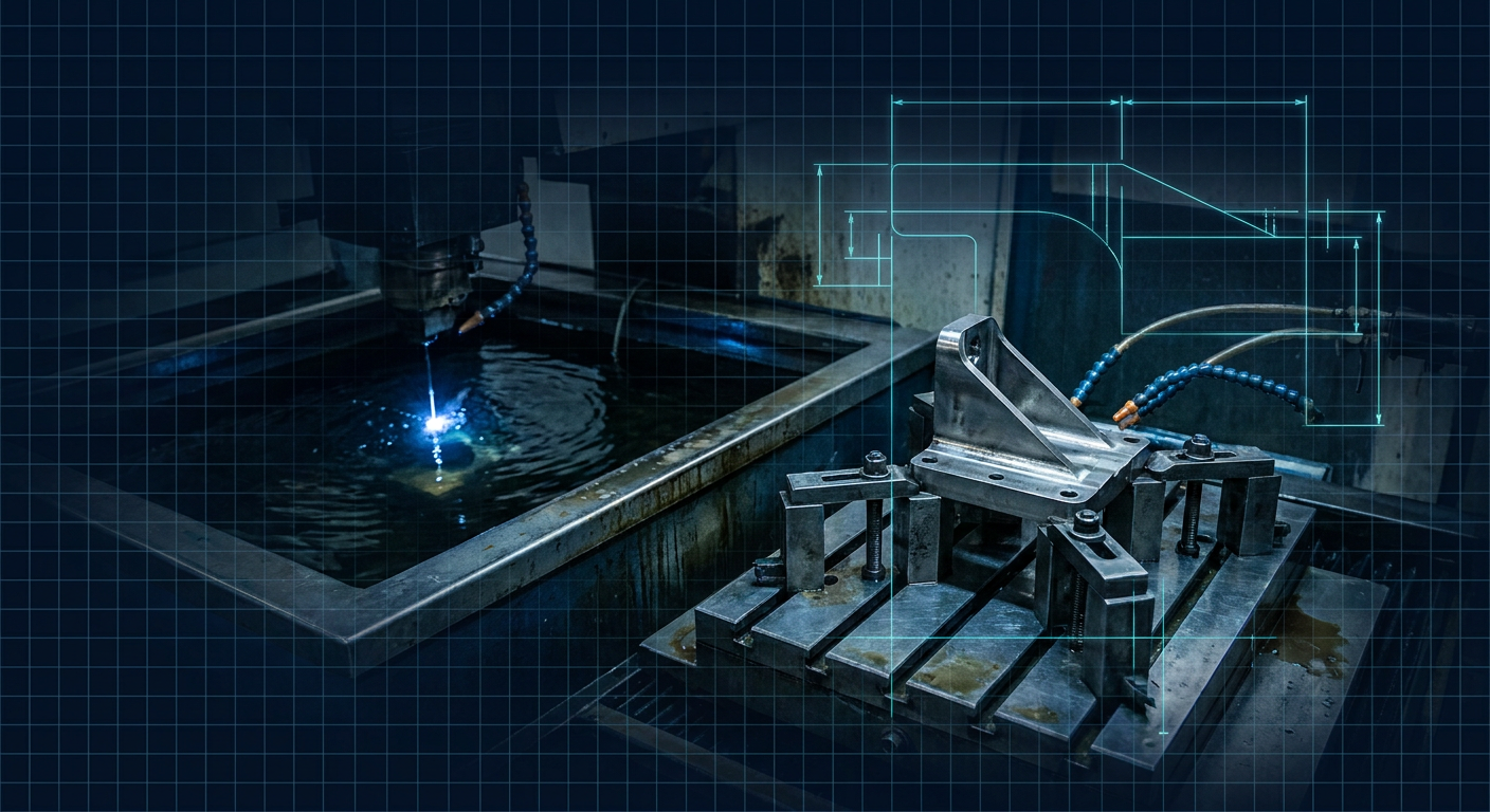
The standard extraction method is submerged Wire Electrical Discharge Machining (wire EDM). The entire plate is clamped into a wire EDM tank, zeroed, and sliced horizontally across the support interface. A typical 400 x 400 mm build plate cut-off takes 4 to 8 hours of EDM cycle time. At shop rates of $90 to $130 an hour for EDM work, you are spending hundreds of dollars just to separate the blanks from the machine.
Support Structure Removal and Surface Finishing
Generative design algorithms create overhangs that must be anchored to transfer heat into the build plate and prevent upward thermal curl. These supports are solid metal trusses.
After wire EDM, a machinist sits at a bench with pneumatic chisels, die grinders, and deburring wheels to grind off the support stubs. This is purely manual labor. It takes between 30 minutes and 3 hours per part depending on accessibility. If an organic strut is positioned 15 mm away from a support surface, you cannot get an end mill or a grinding wheel in there without nicking the structural surface.
Furthermore, the as-printed surface roughness (Ra) of LPBF parts sits between 8 and 20 microns. For dynamic fluid passages or O-ring sealing faces, this is completely unusable. You must run abrasive flow machining, chemical polishing, or vibratory barrel finishing to drop the roughness down to acceptable thresholds (Ra 0.8 to 1.6 microns).
Secondary 5-Axis CNC Post-Machining
Every datum, bearing bore, dowel pin hole, and sealing face must be machined. You cannot print an H7 hole tolerance. You cannot print a 0.01 mm perpendicularity callout. You cannot print a 3/8-24 threaded hole that holds aerospace torque specs without tapping or thread-milling it.
Here lies the greatest irony of generative metal printing. To post-machine an organic, jelly-like generative bracket, your CNC programmer must design and mill custom soft jaws or multi-axis fixture nests. Clamping a part that has no flat surfaces, no perpendicular datums, and high surface variation without distorting it under cutting loads is a nightmare.
Setting up the secondary CNC fixture for an organic additive part often takes twice as long as programming the original part from a square billet on a standard 5-axis mill.
The True Unit Cost Breakdown: Additive vs 5-Axis Billet
Let us look at a real-world production component to understand why Nikon took a half-billion-dollar hit.
Consider an aerospace hinge bracket measuring 120 x 80 x 60 mm, manufactured in Ti-6Al-4V (Grade 5). The target production run is 100 units.
- Option A: 5-Axis CNC Milling from Solid Billet.
- Option B: LPBF Metal 3D Printing + Full Post-Processing Pipeline.
Option A: 5-Axis CNC Machined from Billet
- Raw Material: Solid Ti-6Al-4V block (130 x 90 x 70 mm, approx 3.7 kg). At $45/kg raw material cost: $166.50.
- CAM Programming & Setup: 8 hours at $110/hr amortized over 100 parts: $8.80 per part.
- 5-Axis Machining Cycle: 45 minutes on a high-speed milling center (Hermle or Matsuura) using dynamic trochoidal milling strategies. Machine rate $140/hr: $105.00.
- Tool Wear & Consumables: Titanium wears carbide quickly. Dedicated roughers, ball mills, and coolant: $28.00 per part.
- Stress Relief / Deburr / Anodize: Batch heat treat and surface finishing: $22.00 per part.
- Total Cost Per Unit (Billet CNC): ~$330.30
- Cycle Time Per Part: Under 1 hour.
Option B: Generative LPBF Metal Print + Secondary Machining
- Raw Material (Powder): Optimized generative part volume yields a 0.85 kg part. Accounting for 15% support mass and 5% powder loss/sieve scrap: 1.05 kg of virgin/recycled Ti powder at $160/kg: $168.00.
- Printer Machine Time: 4 parts per build on a mid-frame LPBF machine (e.g., SLM 280 single/dual laser). 28-hour total build cycle time = 7 hours machine time per part. Machine depreciation, argon gas consumption, electricity, and recoater blades at $65/hr: $455.00.
- Vacuum Stress Relief: Amortized furnace batch run: $35.00 per part.
- Wire EDM Subplate Separation: 4 parts per plate, 5 hours wire cycle time = 1.25 hours per part at $95/hr: $118.75.
- Manual Support Removal & Blasting: 45 minutes of manual bench work at $60/hr: $45.00.
- Post-CNC Machining (Bores & Datums): Custom 3D printed/machined fixture clamping, probe alignment, bore boring, and face milling. 25 minutes setup/run time at $140/hr: $58.30.
- Hot Isostatic Pressing (HIP) Outsource: Density and fatigue compliance: $32.00 per part.
- CT Scanning / Non-Destructive Testing: Amortized sample X-ray inspection for internal void detection: $40.00 per part.
- Total Cost Per Unit (Additive + Post-Ops): ~$952.05
- Cycle Time Per Part: Days to weeks across multiple operational handoffs.
In this realistic batch-production scenario, the additive part costs nearly three times as much as the billet part. The 77% savings in raw material weight achieved by the generative design model saved roughly two kilograms of titanium, which works out to about $90 in un-machined raw stock. But achieving that $90 raw material saving required burning more than $700 in printer depreciation, wire EDM time, manual bench labor, and complex secondary fixturing.
| Process Step | 5-Axis Billet Milling (100 qty) | Generative LPBF Additive (100 qty) |
|---|---|---|
| Raw Stock / Powder | $166.50 (3.7 kg billet) | $168.00 (1.05 kg powder) |
| Primary Shaping (CNC vs Print) | $105.00 (45 min cut) | $455.00 (7 hr print) |
| Stress Relief / Heat Treatment | $22.00 | $35.00 |
| Build Plate Separation (EDM) | $0.00 | $118.75 |
| Support Removal & Bench Work | $0.00 | $45.00 |
| Secondary Precision CNC Ops | Included in step 2 | $58.30 |
| HIP & Non-Destructive Testing | $0.00 | $72.00 |
| Setup & Programming Amortization | $8.80 | Included |
| Tooling & Consumables | $28.00 | Included |
| Total Estimated Unit Cost | $330.30 | $952.05 |
Why Generative AI Without DFM Fails
The fundamental disconnect in modern engineering offices is the separation between generative optimization math and shop-floor reality.
Most generative design engines are pure structural finite element analysis loops. They optimize for stress tensors, stiffness-to-weight ratios, and deflection limits. They treat empty coordinate space as frictionless and free.
When an algorithm generates a smooth, double-curved truss spanning three axes, it does not know that an end mill cannot reach the back face without a custom $4,000 5-axis fixture. It does not know that a downward-facing 30-degree overhang will experience thermal sink failure unless dense scaffold supports are printed underneath it. It does not know that the human operator cleaning that part has to spend 40 minutes with a pencil grinder trying not to scratch the main load path.
Generative mechanical tools, including what we are working on with Mexaio AI, have to treat the manufacturing constraints as hard boundary conditions rather than post-process suggestions. If a generative system proposes a geometry for additive manufacturing, it must simultaneously compute the build orientation, calculate the exact volume and cost of support material, check for line-of-sight tool clearance for post-machining operations, and spit out the true multi-step unit cost before you ever commit a laser to a powder bed.
If the generative tool outputs a part that cannot be held in standard machine vises or requires $500 in wire EDM operations to extract, it is not an intelligent design tool. It is an unconstrained FEA graphics demo.
Where Metal Additive Actually Makes Sense
Nikon writing down SLM Solutions does not mean metal additive manufacturing is dead. It means the market has stopped believing that LPBF will replace traditional subtractive manufacturing for general machine components.
Metal additive has an unbreakable hold on specific niches where the functional geometry is impossible to produce by any other means, regardless of cost:
- Conformal Cooling Channels in Injection Molds: Tooling inserts with curved internal cooling channels that follow the exact contour of a mold cavity reduce injection cycle times by 20% to 40%. In high-volume plastics production, saving 4 seconds on a cycle that runs two million times a year justifies a $5,000 3D printed H13 tool steel insert every single day.
- Rocket Combustion Chambers and Turbomachinery: In modern commercial space propulsion, parts like copper-jacketed thrust chambers with hundreds of micro-cooling passages simply cannot be milled on a 5-axis machine. The consolidation of 40 brazed assemblies into a single printed monolithic structure justifies the machine cost.
- Orthopedic Implants: Titanium hip cups and spinal cages that require trabecular porous structures to promote direct human bone in-growth can only be made using laser or electron beam powder bed fusion. You cannot machine stochastic open-cell porosity on a mill.
- Consolidation of Extreme High-Part-Count Assemblies: When an aerospace ducting assembly consists of 30 stamped sheet-metal components, 4 welded flanges, and 60 rivets, printing a single thin-walled unit eliminates assembly labor, inspection steps, and joint leak paths. The cost comparison here is not printed part versus milled part; it is printed part versus eighty manual assembly steps.
What to Calculate Before Printing Your Next Metal Part
Before you send an organic generative metal part to an internal machine or an external additive bureau, run this checklist on the total manufacturing sequence:
- Calculate the true post-processing cost ratio: If your print quote is $800, budget at least another $600 to $1,000 for build plate cut-off, thermal processing, support grinding, and final bore/thread machining.
- Evaluate 5-axis billet cycle times with modern CAM: Modern adaptive clearing paths remove material at speeds that make raw mass savings less valuable than machine run time. If a CNC can hog out 7075-T6 aluminum or 17-4 PH steel in 40 minutes, cutting a block will almost always beat melting powder for 14 hours.
- Verify datums and clamping access: Look at your generated CAD model. Where will the 5-axis machinist place the three reference probing points? How will the part be clamped without crushing thin-walled generative struts? If there are no parallel faces, add sacrificial machining lugs directly to your model that can be milled off in the final operation.
- Check the build angle overhang limits: Keep every surface above 45 degrees relative to the build plate. The moment you drop below 45 degrees, you need support structures, which destroys surface finish and adds manual grinding labor.
Metal 3D printing is an extraordinary capability for parts that cannot be manufactured any other way. But as an everyday replacement for precision billet machining, the shop-floor physics and post-processing economics remain completely unforgiving.