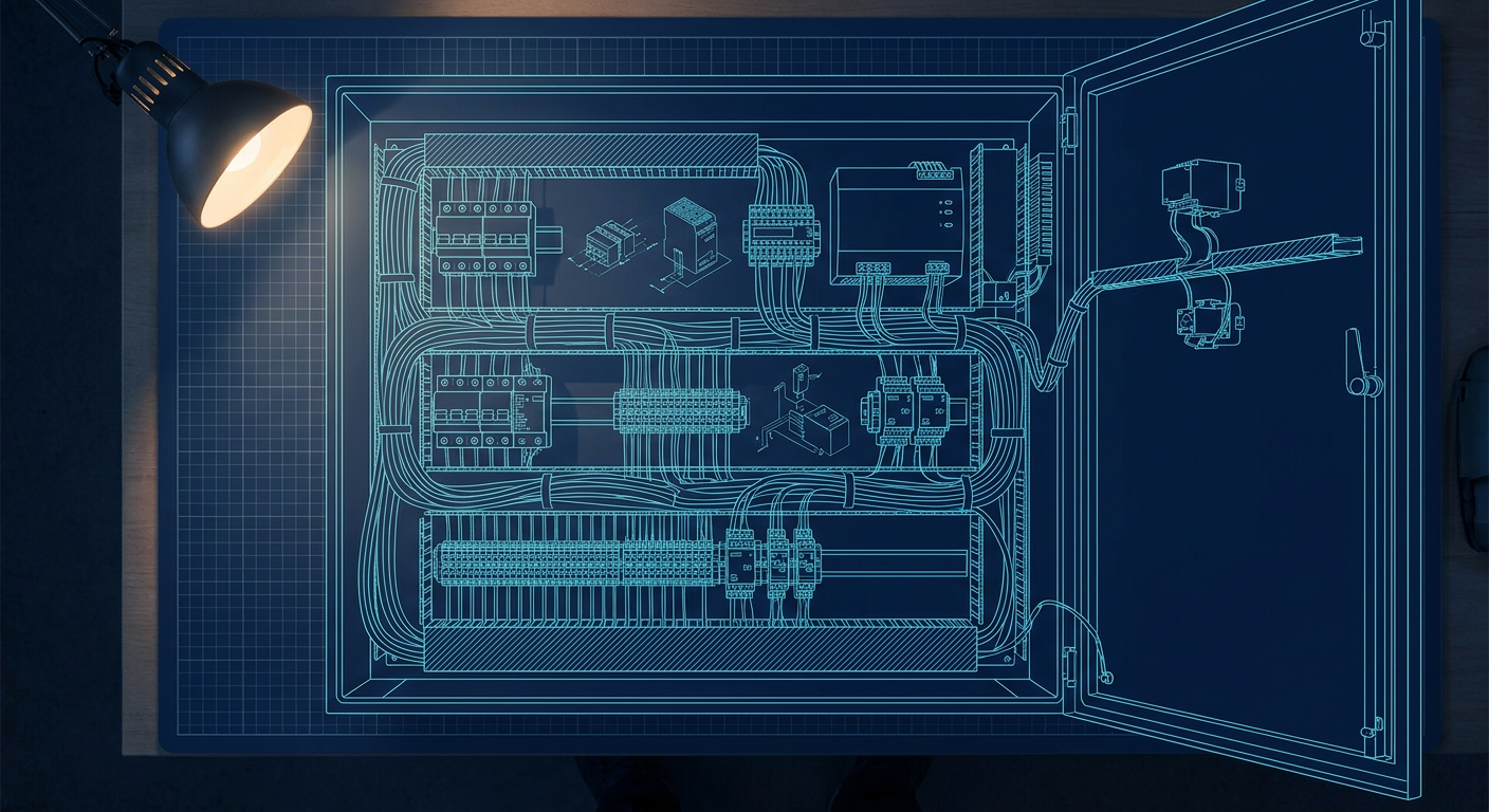
If you build custom automated machinery, pick-and-place rigs, or robotics cells, you have probably lived through this exact scenario. The mechanical assembly is done. The kinematic code runs cleanly in simulation. You wired up the stepper drives, the 24V power supplies, and a compact safety relay onto a backplate inside an off-the-shelf steel enclosure. Everything powers on at your bench, the motors spin, and the emergency stop cuts power as expected.
Then the panel arrives at a customer facility or a third-party testing agency, and the project stops cold. An inspector asks for the Short-Circuit Current Rating (SCCR) calculation, wants to know why you used 1.5 mm² wire behind a 32A upstream breaker, and asks for proof that the main disconnect meets IEC 60204-1 under loaded conditions.
For a mechatronics engineer or a small hardware team without a dedicated electrical panel builder, this standard feels like a dense maze of cross-references, derating curves, and thermal math. Most teams either pay thousands of dollars to an external compliance consultant for a three-page calculation or guess the breaker sizes and hope nobody asks for the documentation.
Neither approach is great. Over the last two years, panel sizing tools like the integrated electrical dimensioning engines inside Siemens TIA Selection Tool have automated most of this math. But to use automated tools effectively, you still need to understand what the software is calculating under the hood.
IEC 60204-1 Versus IEC 61439
The first source of confusion for non-specialists is figuring out which standard applies to the box you just built. You will frequently see two numbers thrown around: IEC 60204-1 and IEC 61439.
The distinction is straightforward in practice:
IEC 61439 applies to low-voltage switchgear and controlgear assemblies meant for general electrical power distribution. If you are building a main electrical distribution board for a building or a motor control center that feeds an entire factory floor, that is IEC 61439 territory. It involves strict laboratory type-testing requirements and structural busbar temperature rise verifications.
IEC 60204-1 applies specifically to the electrical equipment of industrial machines. If your panel controls actuators, motors, sensors, heating elements, or robotic arms, and it forms an integral part of that machinery starting from the point of connection to the supply network, you are designing under IEC 60204-1.
Under IEC 60204-1, you do not need to send your one-off custom enclosure to an external test lab for destructive short-circuit testing. Instead, the standard permits design verification through calculations, adherence to strict component selection rules, and standard engineering tables. That is good news for fast-moving hardware teams, provided you document the numbers correctly.
The Three Sizing Hurdles That Trip Up Generalists
When a mechatronics engineer designs a control enclosure, mistakes rarely happen on the digital logic side. Digital inputs and 24V relay coils are forgiving. The mistakes almost always happen in the power distribution section, specifically across three areas:
- Sizing the main incoming disconnect switch and its supply branch protection.
- Wire cross-section sizing after accounting for internal enclosure heat and wire packing ducts.
- Determining the short-circuit current rating (SCCR) of the complete panel.
Let us walk through each one with real hardware numbers.
1. Sizing the Incoming Disconnect Switch
IEC 60204-1 requires a main supply disconnecting device that can isolate all electrical equipment of the machine from the power supply. For panels with a single incoming line, this is typically a rotary switch-disconnector (like a Siemens 3LD series, an ABB OT series, or an Eaton P1) or a molded case circuit breaker (MCCB) operated via a door-mounted rotary handle.
The common mistake is simply adding up the nominal continuous current of every device in the box and buying a switch that matches that exact sum. That produces an undersized switch that will nuisance-trip or overheat during motor startup.
To size the main disconnect correctly, you need three figures from your bill of materials:
First, calculate the Full Load Current (FLC) of your continuous loads. This includes your 24V DC regulated power supplies, panel cooling units, cabinet lighting, and auxiliary control circuits.
Second, find the rated full-load operational current of all motors or variable frequency drives (VFDs) running simultaneously under normal duty.
Third, identify the single largest motor or drive in the enclosure and look up its starting current or peak locked-rotor current (LRC). For direct-on-line (DOL) induction motors, starting current is typically 6 to 8 times nominal current. For VFD-fed motors or servo drives, this is the peak short-duration input current, usually 150% to 200% of nominal drive rating for a few seconds.
The main disconnect must have an operational current rating ($I_e$) at least equal to the sum of:
- 100% of the full-load current of all continuous and auxiliary loads,
- 100% of the full-load current of all simultaneously operating secondary motors, and
- The starting/peak current of the single largest motor in the system.
If you have three 1.5 kW servo drives (nominal 4.2A input each at 400V 3-phase, with a 200% 2-second peak rating of 8.4A), plus two 24V/10A switched-mode power supplies (pulling 1.2A at 400V 3-phase combined), your sizing calculation is:
$$\text{Minimum Rating} = 1.2\text{A (auxiliary)} + (2 \times 4.2\text{A}) + 8.4\text{A (largest drive peak)} = 18\text{A}$$
You do not buy a 16A disconnect switch. You step up to the next standard industrial frame size, which is 25A or 32A.
Furthermore, IEC 60204-1 specifies the utilization category. If your disconnect switch is also meant to break locked-rotor motor current in an emergency, it must be rated for AC-23B (switching of motor loads or other highly inductive loads), not just AC-21A (switching of resistive loads). Buying a cheap 20A switch rated only for AC-21A will fail an inspection if it is placed in front of dynamic motor drives.
2. Wire Sizing and Thermal Derating Inside Narrow Ducts
In mechatronics prototyping, teams often reach for standard copper hookup wire: 0.75 mm² (roughly AWG 18) for DC signals, 1.5 mm² (AWG 16) for small loads, and 2.5 mm² (AWG 14) for power drops. You pick these because they fit standard ferrule crimpers and terminal blocks.
Under IEC 60204-1 (specifically Section 12 and Table 5/Table 6), conductor sizing is dictated by thermal limits. Wire insulation degrades when subjected to sustained elevated temperatures. The nominal current-carrying capacity listed on a wire spool is usually rated for a single isolated conductor in free air at 30°C ambient. A control panel is the polar opposite of free air at 30°C.
Inside a sealed IP54 or IP65 automation panel, two derating factors immediately hit your wire capacity:
Ambient Air Temperature Derating ($k_1$)
Most industrial factory floors sit at 25°C to 35°C. However, the air inside an operating control box containing two servo drives, power supplies, and a PLC will routinely reach 45°C to 55°C unless you run an active air conditioner. Under IEC 60204-1 Table 6, standard PVC-insulated wire (rated 70°C conductor limit) running in a 45°C ambient enclosure must be derated by a factor of 0.71. If internal enclosure temperatures reach 50°C, the derating factor drops to 0.61. A wire that could carry 15A at room temperature can now safely carry only 9.1A.
Grouping and Duct Packing Derating ($k_2$)
Industrial panels rely on slotted PVC wiring ducts (such as Panduit or Betaduct) to keep wiring neat. When you bundle 10, 15, or 20 current-carrying power conductors together into a single packed duct, they trap heat from adjacent wires.
Under IEC 60204-1 derating tables, routing 6 to 9 loaded conductors in the same trunking requires an additional derating factor of roughly 0.60 to 0.70.
Let us see what happens when you combine these two factors on a 2.5 mm² PVC copper conductor feeding a 3-phase heater or motor:
- Base rating of 2.5 mm² PVC (Installation Method B2, in conduit/duct) at 30°C: roughly 17.5A.
- Temperature derating for 45°C internal ambient ($k_1$): 0.71.
- Grouping derating for 8 loaded conductors in a duct ($k_2$): 0.65.
$$\text{Safe Current Capacity} = 17.5\text{A} \times 0.71 \times 0.65 = 8.07\text{A}$$
Suddenly, your 2.5 mm² wire, which looked perfectly safe on a distributor catalog page for a 14A load, is thermally overloaded at 8.1A. If you run 14A through it for hours, the insulation will harden, turn brittle, and eventually short against adjacent lines or the DIN rail.
To fix this without blowing up your duct sizing, you either:
- Increase the conductor cross-section to 4 mm²,
- Switch to high-temperature insulation wire such as XLPE or silicone rated for 90°C or 105°C (which allows higher current before insulation breakdown), or
- Separate AC motor power wiring and low-voltage DC logic wiring into dedicated, uncrowded ducts.
3. The SCCR Puzzle: Why Miniature Circuit Breakers Fail Verification
The Short-Circuit Current Rating (SCCR) is the maximum prospective symmetrical fault current that an electrical panel or component can safely withstand without causing a fire, exploding, or welding its contacts shut during a dead short.
Here is how small engineering teams get trapped. You pick a line of standard DIN-rail Miniature Circuit Breakers (MCBs), like standard 1-pole or 3-pole 10A DIN breakers. You check the datasheet, see "Breaking Capacity: 6 kA" (or 10 kA according to IEC 60898/60947-2), and assume the panel can be plugged into any standard industrial wall feed.
Then the panel is installed on a factory floor where the supply transformer delivers a prospective short-circuit fault current of 25 kA or 50 kA. If a short-circuit occurs inside your box, the available energy exceeds the physical breaking capability of that 6 kA MCB. The internal contacts can vaporize, the arc chute can blow out of the plastic casing, and the entire panel backplate can catch fire before the upstream building substation breaker even registers the fault.
Under IEC 60204-1:2016 and the 2021 amendments, you are explicitly required to verify the short-circuit withstand rating of the electrical equipment. You have three ways to achieve compliance:
- Full panel calculation using point-to-point impedance: Calculate the exact loop impedance from the incoming terminals through every branch to demonstrate that short-circuit current cannot exceed the lowest-rated device.
- Type-tested combinations (Coordination Tables): Use components from a single manufacturer that have been tested and certified together.
- Current-limiting upstream devices (Series Rating / Cascading): Place an approved high-speed current-limiting fuse or molded case breaker directly at the incoming supply point to choke prospective short-circuit current before it reaches the lower-rated downstream breakers.
For a small team, option 2 and option 3 are the only realistic paths.
If you pair a standard 6 kA or 10 kA MCB with an upstream current-limiting fuse (such as a Class CC or standard IEC NH/gG fuse) or a coordinated MCCB specified by the switchgear manufacturer, the upstream device limits the peak let-through current ($I_{peak}$) and let-through energy ($I^2t$). Under manufacturer coordination tables, that 6 kA MCB is now certified for use in an installation with 50 kA or 100 kA prospective fault levels.
If you mix and match random brands, you lose that certified coordination. If you place a Brand A fuse in front of a Brand B miniature breaker and a Brand C motor contactor, no manufacturer will provide a combination rating table for that setup. You are left with the lowest rating of any individual component in the box, which is often a 4.5 kA or 6 kA MCB. The overall SCCR of your entire machine panel is then marked as 6 kA, which many modern manufacturing plants will reject at commissioning.
| Component Configuration | Typical Native Rating | Upstream Protection | Coordinated SCCR Result |
|---|---|---|---|
| Mixed-vendor MCB + Contactor | 6 kA to 10 kA | None / Uncoordinated | 6 kA (Weakest link limits entire panel) |
| Tested Combination (e.g. Siemens SIRIUS 3RV2 + 3RT2) | 10 kA to 65 kA | Matched 3VA MCCB / Class J Fuse | Up to 100 kA based on manufacturer tables |
| Drive / Inverter Branch | 5 kA | Standard Fast-acting Semiconductor Fuses (gR/aR) | 65 kA to 100 kA depending on drive OEM specs |
How Automated Sizing Tools Do the Math
Until recently, calculating loop impedances, let-through energy curves, and thermal deratings required spreadsheets or expensive software suites like EPLAN Pro Panel with supplemental calculation add-ons.
Siemens and other major automation vendors have pushed these engineering calculations directly into free configuration software. Within the Siemens TIA Selection Tool, the Integrated Control Panels (ICP) and Electrical Designer modules handle IEC 60204-1 and IEC 61439-2 sizing calculations automatically as you select field devices.
Here is how the automated workflow actually operates:
Load Definition and Supply Network Configuration
You do not start by picking a breaker. You start by defining your machine's power supply: line voltage (e.g., 400V 3-phase, 50 Hz), grounding scheme (TN-S, TN-C, or IT), and prospective short-circuit current at the feed point (e.g., 50 kA).
Then you attach your mechanical loads: a 3 kW conveyor motor with DOL start, two 1.5 kW positioning axes driven by servo converters, a 4 kW hydraulic pump running continuously, and a 24V DC / 40A power supply for sensors, safety controllers, and I/O slices.
Automated Cable and Branch Calculation
The software checks the rated current and operational duty of each motor and drive. It automatically selects the motor protection circuit breaker (MPCB), the contactor, and the appropriate overload relay class (Class 10 for normal starts, Class 20 for heavy-inertia loads).
Next, it calculates the minimum cable cross-section between the panel terminals and the motor, taking into account user-defined parameters: cable length, installation method (tray, conduit, bundle), and operating ambient temperature. If a 30-meter cable run causes more than a 3% voltage drop during motor starting, the tool automatically steps the conductor size from 2.5 mm² up to 4 mm² to stay within IEC limits.
Automatic SCCR Cascading
Because the software references a verified database of manufacturer combination tests, it checks whether the chosen branch protection devices (like SIRIUS 3RV motor starters or 3VA molded case breakers) are coordinated with the incoming main disconnect. If a downstream branch breaker only has a 10 kA breaking capacity but the line supply is 50 kA, the tool flags the mismatch and suggests the exact upstream backup fuse or MCCB required to elevate the entire branch combination to 50 kA.
Enclosure Thermal Balance
Every component added to the bill of materials has a known power dissipation rating (in Watts) stored in its component metadata. When a motor contactor is closed, its coil consumes 4W and its power poles dissipate 6W under load. A 24V/40A switched-mode power supply operating at 92% efficiency dumps roughly 80W of heat into the box.
The tool totals the aggregate thermal dissipation of all power supplies, drives, contactors, and terminal blocks. Based on your target enclosure dimensions (height, width, depth), material (painted sheet steel vs. stainless steel), and installation location (free-standing, wall-mounted, or recessed), the tool calculates whether passive heat radiation through the enclosure surface is sufficient.
If the internal air temperature exceeds 40°C or 50°C, the software warns you that your wire derating factors and electronic device lifespans are compromised. It then automatically dimensions the necessary filter fans or thermoelectric cooling unit to bring the cabinet back within standard operating limits.
Where Automated Tools Fall Short
While automated tools save hours of spreadsheet math, they have obvious blind spots that you need to watch out for.
First, vendor sizing tools are built to sell that specific vendor's components. If you use Siemens TIA Selection Tool, it works smoothly as long as your disconnect, contactors, overloads, and drives are Siemens parts. If you are building a hybrid panel that mixes a Beckhoff IPC, a Delta servo drive, an Omron safety controller, and Mean Well power supplies, the automated coordination calculation breaks down. The software cannot verify SCCR combinations for third-party parts.
Second, automated tools do not see physical layout geometry inside your enclosure. The software may calculate that your total wire duct packing density is acceptable based on total panel volume, but it will not notice that you routed a high-current 400V spindle line right next to an unshielded analog 0-10V sensor wire in the same vertical duct.
When we configure control panels in LabCD for automated I/O synthesis and hardware validation, keeping low-voltage fieldbus lines physically separated from noisy drive power output lines remains a strict physical layout rule that no cloud sizing wizard can enforce for you.
Step-by-Step Verification Without a Consultant
If you are finishing a machine panel and need to produce an IEC 60204-1 compliance packet without spending five figures on an outside engineering firm, follow this straightforward verification sequence:
Step 1: Create a Single Line Power Hierarchy
Draw a clean one-line diagram showing the incoming supply down through the main disconnect, the busbar distribution, branch fuses/breakers, and ending at the load terminals. Mark the rated operational current ($I_e$), breaking capacity ($I_{cu}$ or $I_{cn}$), and tripping curve (Type C for general loads, Type D for high-inrush inductive transformers/drives) for every device.
Step 2: Establish the Weakest-Link SCCR
List every power component connected directly to the incoming 3-phase line. Record its short-circuit breaking capacity. If you do not have tested manufacturer coordination data between your main breaker and your branch devices, your panel SCCR is legally equal to the lowest rated component in that power path. Clearly mark this SCCR on the panel nameplate (for example, "Short Circuit Current Rating: 10 kA at 400V").
Step 3: Document Wire Sizing with Derating Factors
In your electrical schematic cable schedule, document the cross-section of all power conductors along with their calculated current carrying capacity after applying ambient temperature ($k_1$) and grouping ($k_2$) derating factors. Ensure that the upstream breaker rating for that branch is equal to or lower than the derated capacity of the wire it protects.
Step 4: Verify Protective Bonding Resistance
IEC 60204-1 requires that all exposed metal parts of the enclosure, doors, subpanels, and machine chassis are bonded to the main protective earth (PE) terminal. With the panel unpowered, use a calibrated low-resistance ohmmeter (applying a test current of at least 10A at 50/60 Hz). Measure the resistance between the PE incoming terminal and every enclosure door, mounting plate, and external metal frame. The measured resistance must not exceed 0.1 ohms.
Step 5: Generate the Machine Nameplate
Print and rivet a durable, non-fading rating plate to the exterior of the enclosure near the main disconnect handle. Under IEC 60204-1 Section 16, this plate must clearly state:
- Manufacturer name and machine identification,
- Supply voltage, phase count, and frequency,
- Full Load Current (FLC) of the largest load plus simultaneous auxiliary loads,
- Panel Short-Circuit Current Rating (SCCR),
- Enclosure IP rating (e.g., IP54 or IP65).
When an industrial customer or field inspector looks at a machine enclosure, they are not looking for perfection. They are looking for evidence of deliberate engineering discipline. Having an organized drawing package, a clear thermal and wire derating calculation, and a documented SCCR verification sheet on file turns an electrical inspection from a multi-week project blocker into a standard ten-minute sign-off.
Sources
- https://www.siemens.com/en-us/industries/industrial-machinery/panel-building-electrical-designer/
- https://industrialmonitordirect.com/blogs/knowledgebase/iec-60204-1-and-iec-61439-control-panel-engineering-reference?srsltid=AU7gw4UqtK8oCpqU2HTr84zkseyLI2tBOu1sy5fAlzsvHZY13MiWmadp
- https://www.gt-engineering.it/en/technical-standards/en-iec-standards/en-iec-60204-1-safety-of-machinery-electrical-equipment-of-machines/amendment-iec-60204-1-2021-gt-engineering-english/
- https://www.idec.com/en-eu/solutions/safety/law/iso-iec/iec60204