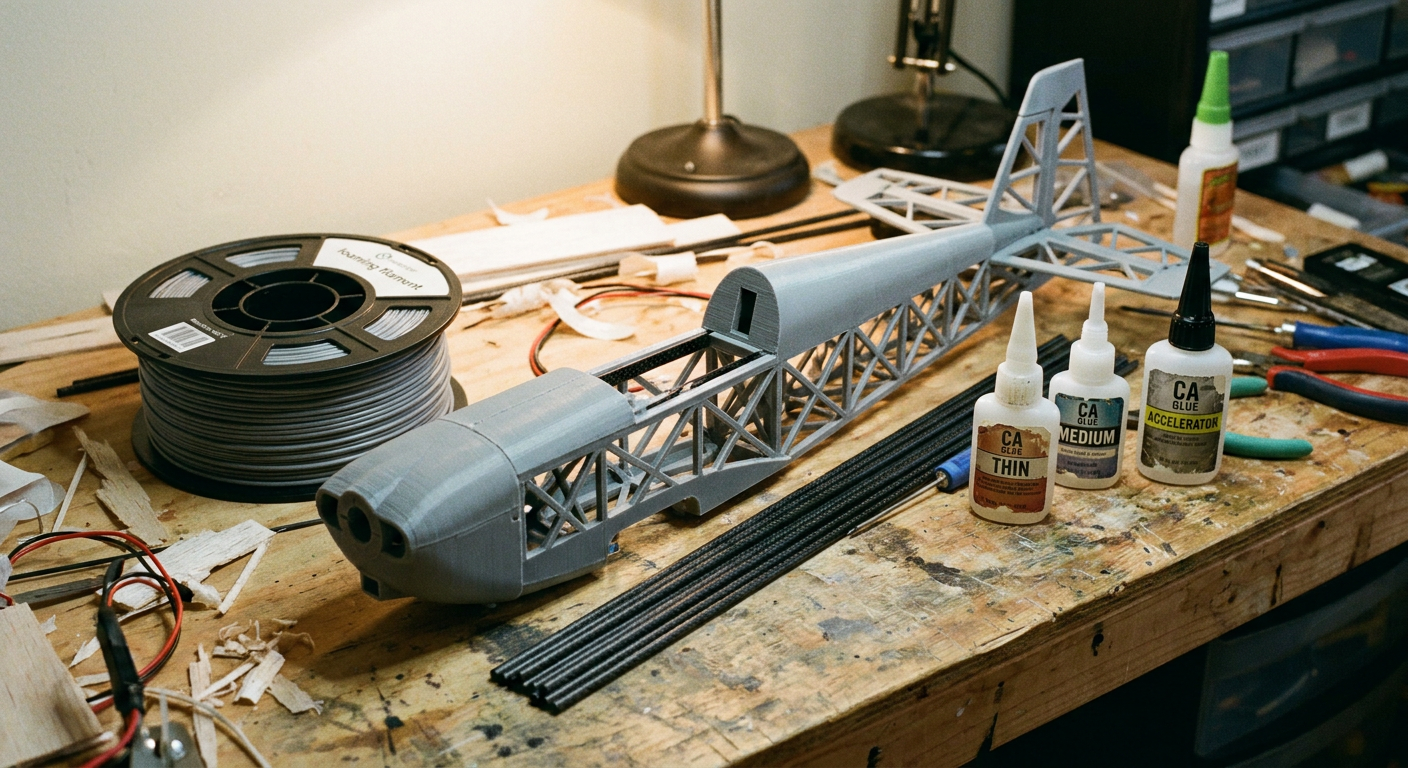
You spent four days printing wing panels, fused the fuselage sections together with medium CA, tuned your center of gravity, and had a great maiden flight. The plane tracked straight, felt light on the sticks, and climbed with plenty of authority. Then you set up your landing approach over the club grass strip. You flared two inches above the turf, the belly settled into the green, and you heard that sickening plastic crunch.
When you walked over to pick it up, the nose had sheared clean off right at the firewall, and the rear fuselage broke into three rings along the print lines.
Every builder getting into 3D printed model aviation goes through this exact cycle. You download a beautiful CAD model from 3DLabPrint or Cults3D, buy a spool of active foaming lightweight filament, and get hooked on the magic of watching a hollow wing section emerge from your print bed. The finished model looks like a factory composite airframe on the bench. On the field, though, a standard grass landing that an old molded foamie would shrug off turns a printed plane into confetti.
Fixing this does not mean giving up on 3D printing or going back to heavy solid PLA. It comes down to understanding why foaming plastics behave the way they do, where print orientation betrays you, and how to combine printed shells with carbon spars and tough materials in the high-stress zones.
The Problem with Active Foaming Filament
For years, printing RC planes with standard PLA was a compromise. Standard PLA has a density around 1.24 grams per cubic centimeter. A four-channel warbird printed in standard PLA ends up heavy, with high wing loading and twitchy stall characteristics. You have to fly it fast, land it fast, and pray you do not stall on base-to-final turn.
Active foaming materials, like colorFabb LW-PLA or 3DLabPrint PolyLight 1.0, changed the hobby by adding a chemical blowing agent to the resin. When you heat the nozzle past roughly 210 degrees Celsius, the blowing agent activates and releases gas. The plastic expands inside the nozzle and foams as it extrudes, swelling up to two or three times its original volume.
By dropping your flow rate down to 45% or 50% in your slicer and running the hotend between 230 and 250 degrees Celsius, you cut the finished part weight by half. A printed warbird suddenly has the wing loading of a standard balsa or foam model.
There is an engineering penalty that filament manufacturers rarely highlight on the product page. Foamed plastic is full of micro-bubbles. Those bubbles lower the density, but they also reduce the surface contact area between your extruded layers. Standard PLA layer adhesion is already the weakest axis of any 3D print. When you fill that layer interface with gas bubbles, your Z-axis tensile strength drops sharply.
A single-wall perimeter printed in foaming LW-PLA is essentially an eggshell. It handles aerodynamic air loads across the curve of an airfoil just fine. What it cannot handle is a point load or a sudden shock, which is exactly what happens when your landing gear catches a thick blade of grass or the nose digs into soft dirt.
Molded EPP Versus Printed Shells
To understand why your printed plane breaks while your five-year-old foam trainer survives cartwheels, compare the materials.
Most commercial ready-to-fly planes use Expanded Polypropylene (EPP) or Expanded Polyolefin (EPO). These foams are molded from tiny beads under steam pressure. EPP is elastic. When an EPP wing hits the ground, the foam beads compress, absorb the kinetic energy, and spring back into shape. If an impact is hard enough to tear EPP, it tears along jagged bead boundaries that you can glue back together with regular contact cement or UHU Por in five minutes.
LW-PLA has almost zero elasticity. It is rigid until it reaches its failure point, and then it shatters.
When an RC plane touches down on grass, the airframe undergoes three distinct mechanical forces:
- Longitudinal deceleration: The friction from the grass grabs the bottom of the fuselage or wheels, pulling backward while the heavy battery inside wants to keep moving forward at 15 miles per hour.
- Torsional twist: If one wingtip touches the grass before the other, the wing acts as a lever arm, twisting the entire fuselage.
- Ground shock: Vertical inertia drives the motor, battery, and radio gear downward into the belly pan.
In a molded foam plane, the foam flexes to dissipate these shocks. In a 3D printed plane, the hollow single-wall fuselage cannot flex. The shock concentrates directly along the weakest printed seam, usually the ring joint where two fuselage segments were glued together, or right behind the motor mount.
Slicer Adjustments That Add Real Strength
Before you change your plane design or add heavy reinforcements, you can gain substantial impact strength simply by changing how your slicer lays down plastic.
Increase Your Extrusion Width
Most default profiles for 3D printed planes assume a 0.40mm line width on a 0.40mm nozzle. Pushing that line width out to 0.50mm or even 0.55mm makes a massive difference in wall rigidity without doubling the weight.
A 0.55mm extrusion width forces more material against the previous layer under nozzle pressure, flattening the bead and increasing the contact surface area. While it increases the weight of a single perimeter by about 20%, you often end up with a part that is twice as stiff.
Print Hotter Than the Minimum Foaming Temp
Many builders tune their LW-PLA temperatures down to 220 degrees Celsius because it reduces stringing and gives a smooth surface finish. The problem is that lower temperatures produce poor layer welding.
Bump your hotend to 240 or 245 degrees Celsius. Yes, you will get more stringing inside the hollow wing bays, but you do not look at the inside of the wing when the plane is flying. The extra heat partially melts the underlying layer as the new one goes down, creating a much stronger weld between print lines.
Slicer Parameter          Default Profile       High-Strength Profile
-----------------------------------------------------------------------
Nozzle Diameter           0.40 mm               0.40 mm
Extrusion Width           0.40 mm - 0.42 mm     0.50 mm - 0.55 mm
Print Temperature         220°C - 225°C         240°C - 248°C
Flow Rate / Extrusion     48% - 55%             52% - 60%
Cooling Fan               50% - 100%            0% - 20%
Turn Down the Part Cooling Fan
Cooling fans are the enemy of layer adhesion. While a blast of cooling air keeps overhangs neat, it chills the newly deposited line of plastic before it can fuse with the layer below it.
For structural airframe components, set your part cooling fan to zero, or at most 20% for steep upper wing skins. Letting the plastic cool slowly gives the polymer chains time to entangle across the layer boundary, drastically improving impact resistance.
Where to Put Carbon Spars
No amount of slicer tweaking will make a single-wall plastic tube survive a hard belly landing without internal help. You need continuous load paths made from carbon fiber.
A lot of beginners stick a three-inch carbon rod into the wing root and call it a day. That actually creates a new failure point. When the wing bends, the rigid carbon rod ends abruptly inside the hollow print, creating a stress riser where the wing skin will snap in two.
WRONG: Short carbon stub creates a stress concentration point
[=== Carbon Stub ===] (Stress Riser Here -> |) [ Empty Printed Wing Skin ]
--------------------------------------------------------------------------
RIGHT: Full-length continuous spar transfers loads to the fuselage
[===================== Continuous Carbon Tube =====================]
Continuous Wing Spars
Your wing spar must extend past the high-stress root area, ideally reaching out to at least 70% of the half-span. A 4mm or 6mm hollow carbon tube glued through pre-modeled internal rib channels carries all the bending moments in flight and cushions ground loops on landing.
When inserting carbon tubes through printed internal ribs, avoid thick 5-minute epoxy if you can help it. Epoxy adds dead weight fast. Use thin or medium CA with a capillary applicator tip, or polyurethane glue (like original Gorilla Glue) that foams slightly to bridge the gap between the printed rib hole and the carbon rod.
The Fuselage Belly Stringer
Most printed fuselages break right behind the wing saddle or right behind the battery tray. That is where the cross-sectional shape changes and stress builds up.
To stop your fuselage from snapping in half on grass:
- Run a 1mm x 3mm flat carbon strip or a 2mm solid carbon rod along the bottom inside seam of the fuselage, extending from the motor firewall all the way back past the trailing edge of the wing.
- Secure it with drops of medium CA every few inches.
- This single carbon strip acts as a tension spine. When the nose digs into the ground on landing and tries to fold the tail forward, the carbon strip takes the tension load and prevents the bottom print layers from pulling apart.
The Hybrid Build Strategy
One of the biggest mistakes in 3D printed RC design is trying to print the entire model out of one filament type. Foaming PLA has a job: making lightweight lifting surfaces and aerodynamic fairings. It is the wrong material for high-vibration mounts, landing gear blocks, and battery floors.
Use a multi-material approach on your next build:
1. Print Motor Mounts in PETG or ABS
Never mount a brushless motor directly to a foaming LW-PLA firewall. The motor heat softens the PLA, and the vibration will wallow out the mounting screw holes within two flights.
Print your firewall and motor standoffs in standard PETG, ABS, or polycarbonate. PETG has much higher layer shear strength and handles motor temperatures up to 75 degrees Celsius without creeping under screw tension. Glue the PETG firewall into the LW-PLA nose using polyurethane glue or medium CA with kicker.
2. Print Landing Gear Brackets in TPU
Rigid plastic landing gear mounts break because they do not give. If you hit a bump, the landing gear wire acts as a crowbar, ripping the mounting block out of the fuselage.
Print your internal gear mounts out of 95A hardness TPU (thermoplastic polyurethane). TPU is practically indestructible. It flexes enough to soak up the landing hit, protects the surrounding thin-wall fuselage, and returns to its original shape immediately.
3. Glass the Belly Pan
A very light strip of 0.75-ounce fiberglass cloth applied with water-based polyurethane (like Minwax Polycrylic) adds almost no weight and completely transforms the durability of a belly-lander.
Cut a 2-inch wide strip of fiberglass cloth. Lay it along the bottom of your fuselage where it rubs against the grass. Brush on a thin coat of water-based polyurethane. It dries clear, does not melt the PLA, and creates a tough skin that stops grass from scratching through the print layers.
Fixing Cracked Prints at the Field
When you do have a rough landing and hear that dreaded snap, do not throw the airframe in the trash bin at the field. 3D printed planes are surprisingly easy to repair if you carry the right kit in your flight box.
Keep three items in your field bag:
- Thin CA glue with a fine needle applicator tip.
- CA accelerator (kicker).
- A roll of 3M Blenderm surgical tape or heavy-duty packing tape.
Because 3D printed breaks usually happen cleanly along layer lines, the parts fit back together like puzzle pieces with zero missing material. Push the broken fuselage sections back together until the print lines seat into each other. Run a bead of thin CA along the seam; capillary action will pull the thin glue deep into the foaming structure within seconds. Hit it with a tiny shot of kicker.
Once the glue sets, wrap a single layer of packing tape around the outside of the break perpendicular to the seam. The tape provides the tensile strength that the broken print lost, letting you get back in the air for your next battery pack without packing up early.
If you want to design your own reinforcements, airframes, or custom mounts tailored to your battery and motor setups, you can check out platforms like MyRC (myrc.ai) for practical RC design workflows and performance sizing before heating up your printer.
Dialing In Your Next Build
If you are slicing an airframe for next weekend, run a quick calibration test first. Do not print an entire 15-hour wing segment to see if your layer adhesion is good enough.
Print a simple single-wall test cylinder that is 50mm in diameter and 100mm tall using your current LW-PLA settings. Let it cool completely. Grab the cylinder with both hands and try to pull it apart like a soda can.
If it snaps cleanly with very little effort, your layer bonding is too cold or your line width is too narrow. Raise your hotend temperature by 10 degrees, push your extrusion width to 0.52mm, drop your part cooling fan to zero, and print another test tube. When you reach the point where the plastic deforms and tears diagonally across the print lines instead of snapping along a single horizontal layer ring, your settings are dialed in.
Take that calibrated profile, run your carbon belly stringers through the high-stress zones, and your printed plane will handle normal field landings week after week.
Sources
- colorFabb: https://colorfabb.com
- 3DLabPrint: https://3dlabprint.com
- CNC Kitchen LW-PLA Testing: https://www.cnckitchen.com/blog/colorfabb-lw-pla-testing-foaming-pla
- Prusa Knowledge Base (LW-PLA Material Profile): https://help.prusa3d.com/article/lw-pla_304914