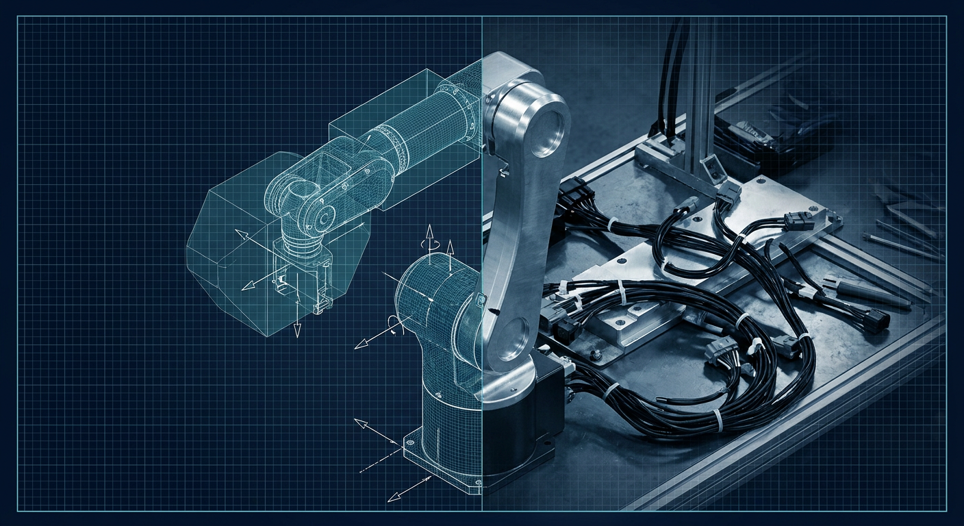
Cutting aluminum for a prototype robot arm before validating dynamic motor loads is an expensive habit.
A standard six-axis articulated arm built for a 3 kg payload usually burns through three iterations before it works cleanly. The first machining batch in 6061-T6 costs around $4,500 at a domestic job shop, plus another $6,000 for strain wave gearheads, frameless brushless motors, magnetic encoders, and custom turning for the bearing housings. You press the bearings into the bores, torque down the cross-roller rings, wire the field-oriented control boards, and run a simple trajectory at 80% rated speed.
Then the elbow actuator stalls on a dynamic deceleration. Or the wrist develops a 1.2 mm chatter at full reach because the planetary gearbox backlash in joint five was not accounted for in your static CAD model.
For years, the standard fix was over-engineering. You bumped up motor frame sizes from 50 mm to 70 mm, stepped up from a 14-size to a 20-size gearbox, added 40% more aluminum to the link walls, and accepted a heavier, more sluggish arm.
Recent pipelines out of NVIDIA research at ICRA and MIT's robotics labs point to a better workflow. By taking CAD assemblies straight into GPU-accelerated simulation environments like Isaac Sim and Isaac Lab, mechanism designers can subject a digital twin to thousands of randomized physical corner cases in minutes. You can test whether a cheap brushless motor will skip steps or overheat under real inertia profiles before sending STEP files to the machine shop.
The Problem with Static CAD and Basic Multibody Dynamics
SolidWorks, Inventor, and Fusion 360 do static calculations well. You get precise mass properties, centers of gravity, and basic interference checks. SolidWorks Motion can calculate theoretical joint torque for a predetermined path.
The issue is that traditional CAD motion studies assume rigid bodies, infinite actuator bandwidth, zero joint friction variation, and ideal control loops. In reality, physical mechanisms suffer from five major non-linearities that static CAD completely ignores:
- Dynamic torque drop-off. Motor torque is not a flat line. It drops as back-EMF builds at higher angular velocities, governed by your bus voltage.
- Contact compliance and joint play. Every gear mesh has backlash. Every bearing race has radial and axial play. When an arm reverses direction under payload, that deadband causes shock loads that trip over-current protection.
- Friction transition. The boundary between static breakaway friction and dynamic Coulomb friction in a sealed harmonic drive creates stick-slip oscillations at low speeds.
- Deflection under payload. Thin-walled aluminum tubes and 3D-printed carbon-nylon links flex under torsional loads, shifting the center of mass.
- Control loop latency. In the real world, your CAN bus or EtherCAT network has 1 to 5 milliseconds of jitter, meaning torque commands always lag reality.
Simulating these non-linearities on a CPU physics engine like ODE or Bullet used to take hours for a single trajectory. If you wanted to test whether an arm could catch a moving payload across 100 different approach angles and joint wear states, you had to run the simulation overnight.
Moving to GPU-Accelerated Synthetic Physics
NVIDIA's Isaac Lab framework changes the economics of mechanism simulation by shifting the physics solver (PhysX 5) directly onto CUDA cores. Instead of running one robot in one virtual room, a single desktop workstation with an RTX 4090 runs 4,096 identical robot arm instances in parallel at tens of thousands of physics steps per second.
This speed allows for heavy domain randomization. You do not just simulate your nominal CAD assembly. You tell the simulation to instantiate 4,096 variations where:
- Link masses vary randomly by plus or minus 12% to account for billet material variations and wiring weight.
- Joint friction coefficients vary by 25% to mimic grease breakdown and temperature swings.
- Actuator backlash varies between 0.02 and 0.15 degrees.
- Motor torque limits are capped to simulate a 15% voltage sag on the DC power supply.
- The payload mass and grip offset shift randomly on every cycle.
If your proposed motor and gearbox combination can successfully hold trajectory tolerances across 99% of those 4,096 randomized environments, the mechanism will work on the physical bench. If joint three fails in 15% of the environments due to torque saturation, you know you need a higher reduction ratio before you order parts from your supplier.
MIT's recent work on synthetic simulation environments builds on this concept by using automated agents to generate dynamic physical edge cases. Instead of an engineer hand-crafting a test trajectory, the environment generates chaotic perturbation profiles: sudden payload drops, joint stalls, high-frequency vibration inputs, and wall collisions. It pushes the mechanical kinematics to the exact breaking point of the actuation envelope.
The Pipeline: From SolidWorks to Isaac Sim
Getting a custom mechanism out of CAD and into Isaac Sim without breaking the physics model requires a disciplined export process. Physics engines do not ingest native SolidWorks .sldasm files; they require Universal Scene Description (USD) or Universal Robot Description Format (URDF) linked with accurate collision meshes.
Step 1: Clean Up the CAD Assembly Hierarchy
Before exporting, strip out non-structural hardware. Delete bolts, washers, internal motor windings, and encoder PCBs from the assembly tree. These components add hundreds of thousands of unnecessary polygons that slow down the physics engine without adding useful dynamic information.
Group your parts strictly by rigid link. If Link 2 consists of two CNC side plates, three standoffs, a bearing retainer, and a motor casing bolted together, combine them into a single rigid sub-assembly or single multibody part in CAD.
Verify that the origin of each sub-assembly sits precisely at the intended joint axis of rotation. A misplaced coordinate system in CAD will result in an eccentric wobble in the physics solver.
Step 2: Generate Clean Collision Geometry
Never use visual CAD meshes for collision detection. A detailed 3D CAD mesh of a machined gearbox housing contains fillets, chamfers, and threaded holes. If PhysX tries to calculate contact manifolds against a 50,000-polygon mesh, the simulation will stall or throw contact instability errors where parts snag on invisible polygon edges.
Instead, export two sets of files for each link:
- Visual Mesh: High-resolution OBJ or USD showing the true part geometry for visual rendering.
- Collision Mesh: Simplified convex hulls.
Use Volumetric Hierarchical Approximate Convex Decomposition (V-HACD) to break complex concave parts into a small cluster of convex hulls. For simple links, manually model primitive bounding boxes, cylinders, and spheres directly in CAD. Primitive shapes calculate contacts significantly faster and prevent physics penetration bugs.
Step 3: Export the Mass Matrix and URDF
Use the SolidWorks to URDF Exporter tool or the NVIDIA Omniverse SolidWorks Connector. Ensure the exporter computes the exact inertia tensor matrix:
$$ \mathbf{I} = \begin{bmatrix} I_{xx} & I_{xy} & I_{xz} \ I_{yx} & I_{yy} & I_{yz} \ I_{zx} & I_{zy} & I_{zz} \end{bmatrix} $$
Many failed sim-to-real transfers happen right here. If your CAD parts are modeled as hollow surface bodies instead of solid volumes with proper material densities (such as 2.7 g/cm³ for 6061 aluminum), your exported inertia tensor will be off by an order of magnitude. The simulated robot will accelerate with unrealistically low motor torque, leading to an under-motored physical build.
Open the resulting .urdf file in a text editor and verify the <inertial> tags for every link. Check that the mass values match reality, especially if you have added batteries, heavy wiring looms, or end-of-arm tooling that were not fully detailed in CAD.
Step 4: Import and Rig in Isaac Lab
Import the URDF into Isaac Sim using the URDF Importer extension. Isaac Sim converts the model into USD format, where you can define the drive dynamics for each joint:
# Isaac Lab Actuator Configuration Example
from omni.isaac.lab.actuators import ImplicitActuatorCfg

joint_actuator_cfg = ImplicitActuatorCfg(
    joint_names_expr=["joint_.*"],
    effort_limit=45.0,         # Maximum torque in Nm
    velocity_limit=3.14,       # Maximum speed in rad/s
    stiffness=800.0,           # Joint stiffness (Kp)
    damping=40.0,              # Joint damping (Kd)
    friction=0.25,             # Static joint friction in Nm
    armature=0.015             # Motor rotor inertia reflected through gearbox
)
The armature parameter is critical. It represents the rotational inertia of the motor rotor multiplied by the square of your gear ratio ($I_{rotor} \times N^2$). For high-reduction gearboxes (like 100:1 strain wave drives), the reflected rotor inertia often dominates the actual inertia of the physical link. Leaving armature out of your simulation will make the simulated robot feel nimble, while the real robot will struggle to accelerate.
Validating Actuator Selection: A Real World Example
Consider designing a 3-DOF pick-and-place wrist. The goal is to move a 1.5 kg machined brass part across a 400 mm span in 0.35 seconds, come to a dead stop, and orient the part with a tolerance of plus or minus 0.05 mm.
You have two motor choices for Joint 1:
- Option A: A direct-drive brushless outrunner (80 mm diameter, 4 Nm peak torque, low rotor inertia).
- Option B: A smaller frameless BLDC with a 30:1 planetary gearbox (45 mm diameter, 18 Nm peak torque, high reflected rotor inertia).
In static CAD, Option A looks risky on torque margin, while Option B looks safe with plenty of holding torque.
You bring both configurations into Isaac Lab, set up a trajectory generator, and add realistic current limits and position loop gains. You run 2,000 parallel test cycles across varying payload surface friction and minor mechanical misalignments.
The simulation results expose the real trade-offs immediately:
| Performance Metric | Option A: Direct Drive | Option B: 30:1 Planetary | Real-World Failure Risk |
|---|---|---|---|
| Move Time (400 mm) | 0.28 seconds | 0.42 seconds | Planetary arm fails cycle time spec |
| Peak Current at Decel | 22 A (within spec) | 34 A (trips driver) | High reflected inertia causes back-EMF spike |
| Settling Time at Target | 18 milliseconds | 95 milliseconds | Gearbox backlash causes position ringing |
| Positional Repeatability | $\pm 0.02$ mm | $\pm 0.12$ mm | Backlash exceeds $\pm 0.05$ mm tolerance |
| Thermal Dissipation | 45 W steady | 18 W steady | Option A runs hotter, needs heatsinking |
Option B fails the cycle time and precision specs due to backlash ringing and reflected rotor inertia during the rapid deceleration phase. Option A runs warmer but hits the positional accuracy and speed cleanly.
Running this test in Isaac Sim took 15 minutes to set up and 45 seconds to compute. Discovering this on the shop floor after cutting bearing plates and waiting three weeks for precision gearboxes would have cost $3,000 and blown the client delivery timeline.
Generative design workflows, like those we run at Mexaio AI to generate lightweight structural linkages, tie directly into this loop. You can generate an optimized, stress-relieved link geometry, immediately push its inertial properties and USD mesh into Isaac Lab, run dynamic stability tests, and adjust wall thicknesses before sending the model to a 5-axis mill or metal 3D printer.
What Simulators Still Miss (And How to Compensate)
Physics simulation has closed the sim-to-real gap significantly, but it is not magic. There are mechanical realities that PhysX 5 and Isaac Sim do not calculate natively:
Cable Harness Drag and Torsion
Thick, braided motor power cables, CAN bus lines, and pneumatic air lines act as non-linear spring-dampers. On small robotic arms (under 2 kg payload), a stiff 12 AWG cable bundle strapped along an elbow joint can exert up to 0.8 Nm of resistive torque at maximum flexure.
Fix: Add an explicit angular spring-damper joint modifier in Isaac Sim with an empirical resistance curve measured from a bench test of your cable bundle.
Thermal Derating of Actuator Windings
Isaac Sim calculates torque and speed, but it does not track copper coil temperatures or neodymium magnet demagnetization curves out of the box. A motor that runs at 10 Nm peak for 10 seconds might survive in sim, but in reality, the stator temperature will cross 120°C and trip thermal cutoff.
Fix: Export the simulated RMS torque and velocity profiles over a 10-minute continuous duty cycle from Isaac Lab into a Python script that applies your motor manufacturer's thermal resistance equations ($R_{th, winding-to-case}$ and $R_{th, case-to-ambient}$).
Housing Deflection Under Shock
Rigid-body simulators assume your bearing journals and structural plates stay perfectly square. If you mount a high-torque actuator to a 3 mm thick 6061 plate without stiffening ribs, the plate will twist under shock loading, misaligning the gearbox shafts and causing binding.
Fix: Run your dynamic peak reaction forces extracted from Isaac Sim back into a static FEA tool to verify that structural deflection remains under 0.03 mm at maximum emergency-stop decelerations.
Setting Up Your Own Simulation Bench
If you run a robotics design office or a mechanical prototype shop, you do not need an enterprise AI infrastructure budget to start validating mechanisms this way. The tooling is largely accessible:
- Workstation Hardware: A single modern workstation equipped with an NVIDIA RTX 4080 or 4090 (24 GB VRAM is ideal for large batch sizes) and 64 GB of system RAM is enough to run Isaac Lab with 2,048 to 4,096 parallel environments.
- Software Stack: Isaac Sim and Isaac Lab are available under NVIDIA's standard developer licensing. You can run them on Ubuntu 22.04 LTS (recommended for clean ROS 2 integration) or Windows 11.
- Model Prep: Keep your CAD to URDF exporter plugins up to date. Verify your coordinate frames and inertia properties on every single export.
Before you send your next complex linkage, custom gripper, or robot joint design to the CNC machine or print farm, take an afternoon to pipe the URDF into Isaac Lab. Drop the link tolerances by 15%, crank up the friction, inject 5 milliseconds of control lag, and see if your motor still makes the move. Finding out in simulation costs twenty minutes of GPU time. Finding out on the shop floor costs your prototype budget.
Sources
- https://blogs.nvidia.com/blog/icra-research-robotics-simulation-to-real-world/
- https://news.mit.edu/2026/ai-agents-create-virtual-playgrounds-to-help-robots-get-crucial-training-data-0713
- https://arxiv.org/html/2511.04831v1
- https://developer.nvidia.com/isaac/sim
- https://x.com/tanayj/article/2087959719247798591