Ask any frontier language model to write an AXI4-Stream skid buffer or a four-phase handshake state machine, and you will almost certainly get code that compiles on the first pass. Verilator will parse it without throwing a fatal syntax error. If you run a quick testbench with five randomized transactions, the waveform might even look clean in GTKWave at first glance.
Put that same code into a formal model checker or run an exhaustive corner-case testbench across backpressure transitions, and the logic breaks. A valid signal deasserts one cycle late. An internal pointer increments twice on a single clock edge because a combinational next-state variable was updated with non-blocking syntax inside an incomplete sensitivity list. Or, worse, an output register samples an intermediate transition state because the model collapsed a three-always-block architecture into a single monolithic block without accounting for register transfer timing.
Autoregressive transformers do not have an internal model of time, concurrency, or signal propagation. They generate text by predicting the next most probable token given the preceding sequence. When applied to Python or C, this sequential bias aligns reasonably well with standard procedural execution models. When applied to hardware description languages, this sequential bias creates systematic, recurring failure modes in sequential and combinational logic partitioning.
Understanding why these failures happen requires looking at how language models misinterpret the IEEE 1800 stratified event queue, where standard static linters fall short, and how embedding formal property verification directly into the generation loop eliminates state machine hallucinations.
The Sequential Token Bias vs the Stratified Event Queue
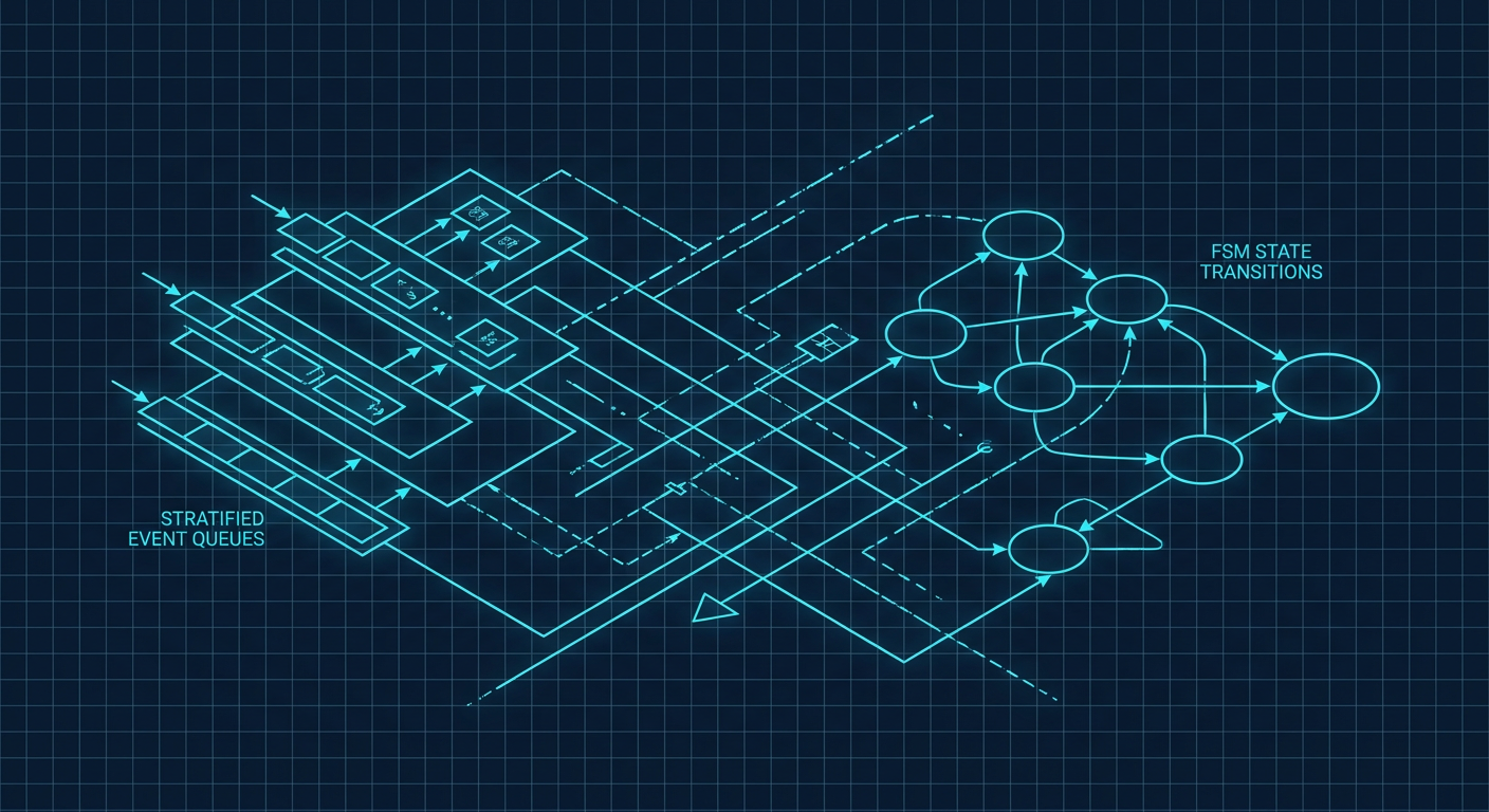
Verilog is not a programming language that executes on a CPU. It is a structural description language that models physical hardware evaluated across discrete simulation time steps divided into execution regions. The IEEE 1800 standard defines a stratified event queue where delta cycles manage causality without advancing simulation time.
Inside a single simulation time step, evaluation passes through several distinct regions:
- Active region: Process blocking assignments (
=), evaluate right-hand side of non-blocking assignments (<=), and run continuous assignments (assign). - Inactive region: Process
#0procedural events. - Non-Blocking Assignment (NBA) update region: Update the left-hand side targets of all non-blocking assignments evaluated in the Active region.
- Observed region: Evaluate concurrent assertions (
assert property). - Reactive region: Process SystemVerilog testbench programs and checkers.
When human engineers write RTL, we maintain a mental model of this physical concurrency. We know that when a clock edge occurs, every register in a synchronous domain reads the value present at its inputs immediately prior to that edge, and the updated output will only become visible to downstream logic in the NBA update phase.
Language models trained predominantly on general software repositories lack this physical abstraction. In Python, if you write:
a = b
c = a
The variable c receives the new value of b immediately. In synchronous Verilog:
always_ff @(posedge clk) begin
    a <= b;
    c <= a;
end
The register c receives the previous value of a, not the value of b that was assigned in the same delta cycle. This shift register behavior is basic to RTL designers, but LLMs routinely mix procedural sequence assumptions with delta-cycle updates.
When prompt contexts grow complex, involving multi-state protocols with handshakes, FIFO watermarks, and credit counters, LLMs often try to resolve multi-variable dependencies by ordering statements procedurally inside clocked blocks. They attempt to write sequential calculations within an always_ff or always @(posedge clk) block as if variables were being updated step-by-step in memory. The result is RTL that introduces unintentional one-cycle latency bubbles, race conditions, or synthesis-simulation mismatches.
Three Common LLM State Machine Traps
Looking at generated RTL across hundreds of state machine implementations reveals three recurring structural errors.
1. The Monolithic Single-Block Trap
LLMs frequently generate one-block state machines where state transitions, combinational decode logic, and registered outputs are all packed into a single sequential always @(posedge clk) block.
// Typical flawed LLM-generated single-block FSM
always_ff @(posedge clk or negedge rst_n) begin
    if (!rst_n) begin
        state      <= IDLE;
        tx_ready   <= 1'b0;
        data_out   <= 32'h0;
        byte_count <= 2'b0;
    end else begin
        case (state)
            IDLE: begin
                if (tx_valid) begin
                    state    <= SEND;
                    tx_ready <= 1'b1; // Latency error: updates one cycle late
                end
            end
            SEND: begin
                if (ack) begin
                    if (byte_count == 2'd3) begin
                        state      <= IDLE;
                        tx_ready   <= 1'b0;
                        byte_count <= 2'b0;
                    end else begin
                        byte_count <= byte_count + 1'b1;
                        data_out   <= next_payload[byte_count]; // Samples stale byte_count
                    end
                end
            end
            default: state <= IDLE;
        endcase
    end
end
In this single-block implementation, tx_ready is registered. It does not go high when tx_valid arrives in IDLE. It goes high on the clock cycle after the state transitions to SEND. Similarly, data_out samples next_payload using the value of byte_count before it increments, because non-blocking assignments defer their update until the NBA region.
While single-block FSMs can be designed correctly by accounting for output registration, LLMs constantly mix Moore and Mealy semantics. They write the state transition logic as if it were combinational while declaring outputs via non-blocking registers, shifting the entire output sequence by one clock cycle relative to the external bus expectation.
2. Blocking Assignments in Sequential Blocks
When an LLM realizes that an output or an intermediate variable must reflect a state transition immediately, it frequently attempts a quick fix: inserting a blocking assignment (=) directly inside an always_ff block.
// Dangerous pattern: mixing blocking assignments in sequential blocks
always_ff @(posedge clk or negedge rst_n) begin
    if (!rst_n) begin
        state <= IDLE;
        cnt   <= 0;
    end else begin
        case (state)
            PROCESS: begin
                cnt = cnt + 1; // Blocking assignment inside sequential block
                if (cnt == 4) begin
                    state <= DONE;
                end
            end
            // ...
        endcase
    end
end
Using blocking assignments inside a sequential block creates severe simulation race hazards. If another concurrent always_ff block reads cnt on the same clock edge, the simulation result depends entirely on whether the simulator schedules the first block or the second block first in the Active region. In synthesis, logic synthesis tools like Synopsys Design Compiler or Yosys will synthesize a combinational path through an internal node into the flip-flop D-input, but the simulation behavior will not match hardware. This introduces a classic synthesis-simulation mismatch that simple testbenches often fail to trigger.
3. Incomplete Sensitivity and Latch Generation in Combinational Logic
When instructed to write standard two-block or three-block FSM architectures, models often produce combinational next-state blocks with unassigned branches or incomplete sensitivity lists.
// Two-block FSM: combinational next-state block
always_comb begin
    next_state = current_state;
    // Missing default assignments for outputs
    case (current_state)
        IDLE: begin
            if (start)
                next_state = RUN;
        end
        RUN: begin
            out_enable = 1'b1; // Latched! Not assigned in IDLE or DONE
            if (done_signal)
                next_state = DONE;
        end
        DONE: begin
            if (ack)
                next_state = IDLE;
        end
    endcase
end
Because out_enable is not assigned in every branch of the combinational always_comb block, synthesis tools infer an unintended level-sensitive latch. In FPGA targets like AMD UltraScale+ or Intel Agilex, transparent latches consume additional routing resources, degrade timing closure, and introduce glitch sensitivity. While always_comb in SystemVerilog forces the simulator to flag latches during compilation, models prompted for legacy Verilog-2001 (always @(*)) will generate these transparent latches silently.
| Failure Mode | Root Cause in LLM | Hardware Symptom | Detection Method |
|---|---|---|---|
| Output Latency Off-by-One | Collapsing combinational decode into clocked register blocks without pre-decode | Bus protocol violation, extra cycle latency on handshakes | Formal assertion on protocol timing (`req |
| Sequential Blocking Assignment | Procedural sequence bias (treating Verilog like C) | Simulation race condition, delta-cycle dependency | Static lint (Verilator/SpyGlass COMBDLY) |
| Combinational Latch Inference | Incomplete case branching without default output assignments | Unintended transparent latch inference, timing closure degradation | Synthesis log parsing, always_comb compiler warnings |
| Glitch on Asynchronous Outputs | Evaluating Mealy outputs in combinational blocks during state transitions | False edge triggers on downstream asynchronous logic | Dynamic simulation with gate-level timing, SVA stability checks |
Why Static Linters Give False Confidence
When teams attempt to build autonomous RTL generation pipelines, their first line of defense is usually a linter. A script runs verilator --lint-only or passes the code through open-source linters like Verible.
Static linters are necessary, but they are insufficient for verifying concurrency. Linters operate on structural abstract syntax trees (ASTs). They catch obvious syntax errors, mismatched bit widths, unused wires, and direct violations like non-blocking assignments inside combinational blocks.
What linters cannot verify is behavioral correctness across state space exploration. A linter cannot tell whether an AXI-Stream tready signal must be asserted combinationally to achieve zero-wait-state line-rate throughput, or if registering it via a skid buffer is required to break a timing path. A linter cannot verify whether an internal FIFO write pointer can wrap around during a simultaneous push and pop operation under a stalled backpressure condition.
Consider a credit-based flow control state machine. The code might pass lint with zero warnings, have perfectly partitioned sequential and combinational blocks, use strictly non-blocking assignments for all registers, and yet contain a deadlock condition where credits drop to zero if a transaction is aborted midway through a packet burst. The syntax is flawless; the protocol logic is broken.
Closing the Loop with Formal Property Verification
To reliably catch concurrency and state transition bugs in generated RTL, verification must move beyond AST linting and fixed dynamic testbenches. The pipeline must generate SystemVerilog Assertions (SVA) alongside the RTL and execute bounded model checking (BMC) in the loop.
Formal verification exhaustively analyzes the mathematical state space of the design up to a bounded number of cycles. Instead of supplying test vectors, the verification engineer (or the LLM orchestration framework) defines formal properties: what must always hold true (invariants) and what must never happen (safety violations).
Here is how an SVA harness exposes an LLM state machine bug that linters ignore.
Assume an LLM generates an arbiter state machine managing two requesters with round-robin priority. We can bind a set of SVA properties directly to the generated module:
module arbiter_sva (
    input logic clk,
    input logic rst_n,
    input logic req0,
    input logic req1,
    input logic gnt0,
    input logic gnt1,
    input logic [1:0] state
);

    // Property 1: Mutual exclusion on grants
    // Grants must never be asserted simultaneously.
    assert_mutex: assert property (@(posedge clk) disable iff (!rst_n)
        !(gnt0 && gnt1)
    ) else $error("Formal violation: Dual grant asserted simultaneously");

    // Property 2: Grant stability
    // If a grant is issued and the requester holds req high, grant must persist until acknowledged.
    assert_gnt0_stable: assert property (@(posedge clk) disable iff (!rst_n)
        (gnt0 && req0) |=> (gnt0 || !req0)
    );

    // Property 3: No phantom grants
    // A grant cannot be issued without an active request.
    assert_no_phantom0: assert property (@(posedge clk) disable iff (!rst_n)
        gnt0 |-> req0
    );

    // Property 4: Liveness / Starvation prevention
    // If req1 is high, it must eventually be granted.
    assert_eventual_gnt1: assert property (@(posedge clk) disable iff (!rst_n)
        req1 |-> ##[1:5] gnt1
    );

endmodule
When we pass the LLM-generated Verilog and this SVA property block into a formal engine like SymbiYosys (using the Yosys + Boolector/Z3 open-source toolchain) or a commercial tool like Cadence JasperGold, the engine does not simulate random inputs. It formulates the entire RTL state machine as a set of Boolean satisfiability constraints.
If the LLM made an error such as forgetting to clear gnt0 when transitioning from STATE_GRANT0 to STATE_GRANT1 during a simultaneous assertion of req0 and req1, the formal tool finds a counterexample in fewer than 4 delta cycles. It outputs the exact sequence of register states and wire valuations that broke the invariant.
Feeding Formal Counterexamples Back into Prompt Context
When formal verification fails, it produces a trace: a cycle-by-cycle valuation of every input, internal state register, and output leading to the assertion failure.
Passing raw simulation waveforms or long VCD files into an LLM context window is inefficient and consumes unnecessary tokens. However, converting the formal counterexample into a structured trace table provides the precise contextual signal the model needs to correct its timing assumptions.
FORMAL VERIFICATION FAILED
Property Violated: arbiter_sva.assert_mutex
Trace Depth: 3 cycles

Cycle 0: rst_n=0, state=IDLE,   req0=0, req1=0, gnt0=0, gnt1=0
Cycle 1: rst_n=1, state=IDLE,   req0=1, req1=1, gnt0=0, gnt1=0
Cycle 2: rst_n=1, state=EVAL,   req0=1, req1=1, gnt0=1, gnt1=1 <-- VIOLATION

Counterexample details:
At Cycle 1, both req0 and req1 asserted.
State transitioned to EVAL.
In state EVAL, non-blocking assignment 'gnt0 <= 1'b1' and 'gnt1 <= 1'b1'
executed concurrently due to missing mutual exclusion in the nested if-else branch.
When an LLM receives this structured counterexample alongside its previously generated code, the error correction accuracy improves substantially compared to generic prompting. The model does not need to guess how its code behaves dynamically; the formal engine has provided the exact state vector that exposes the logical flaw.
In our engineering work on the Silicode generative RTL engine, this closed-loop formal binding forms the backbone of the synthesis validation stage. Rather than relying on standard code generation followed by manual review, every generated sequential block is automatically paired with an assertion template, compiled against an SVA harness, and checked with bounded model checking before the code is presented to an engineer.
Building a Robust State Machine Generation Loop
If you are integrating language models into your hardware engineering workflow or building internal tooling for digital design teams, you must enforce structural rules in the prompting and verification pipeline.
Explicit Structural Prompting Rules
Do not ask a model to simply "write a state machine for protocol X." Provide explicit architectural boundaries in your system prompts:
- Enforce the Three-Block Structure: Mandate that the model separate sequential state transitions, combinational next-state evaluation, and registered output assignments into three distinct procedural blocks.
- Ban Blocking Assignments in Clocked Logic: Set an explicit constraint that all variables declared inside
always_fforalways @(posedge clk)must strictly use non-blocking (<=) assignments. - Require Default Next-State and Output Assignments: Force the model to assign default values to
next_stateand all combinational control signals at the very top of thealways_combblock, prior to entering thecaseconstruct. This mathematically eliminates transparent latch inference. - Mandate Explicit State Encodings: Require the model to declare states using SystemVerilog enumerated types (
typedef enum logic [N:0]) rather than rawparameteror`definemacros. This allows both the compiler and formal tools to verify state reachability and completeness.
Here is a clean reference implementation that demonstrates the correct three-block separation:
// Robust Three-Block FSM Architecture
module fsm_controller (
    input  logic        clk,
    input  logic        rst_n,
    input  logic        start,
    input  logic        abort,
    input  logic        data_ready,
    output logic        busy,
    output logic        out_valid
);

    typedef enum logic [1:0] {
        STATE_IDLE    = 2'b00,
        STATE_PROCESS = 2'b01,
        STATE_DONE    = 2'b10
    } state_t;

    state_t current_state, next_state;
    logic out_valid_nxt;
    logic busy_nxt;

    // Block 1: Sequential state register update
    always_ff @(posedge clk or negedge rst_n) begin
        if (!rst_n) begin
            current_state <= STATE_IDLE;
            out_valid     <= 1'b0;
            busy          <= 1'b0;
        end else begin
            current_state <= next_state;
            out_valid     <= out_valid_nxt;
            busy          <= busy_nxt;
        end
    end

    // Block 2: Combinational next-state logic
    always_comb begin
        next_state = current_state; // Default: hold current state

        case (current_state)
            STATE_IDLE: begin
                if (start)
                    next_state = STATE_PROCESS;
            end
            STATE_PROCESS: begin
                if (abort)
                    next_state = STATE_IDLE;
                else if (data_ready)
                    next_state = STATE_DONE;
            end
            STATE_DONE: begin
                next_state = STATE_IDLE;
            end
            default: begin
                next_state = STATE_IDLE;
            end
        endcase
    end

    // Block 3: Combinational output decode (registered in Block 1 for clean timing)
    always_comb begin
        out_valid_nxt = 1'b0; // Default output values
        busy_nxt      = 1'b1;

        case (current_state)
            STATE_IDLE: begin
                busy_nxt = 1'b0;
                if (start)
                    busy_nxt = 1'b1;
            end
            STATE_PROCESS: begin
                busy_nxt = 1'b1;
            end
            STATE_DONE: begin
                out_valid_nxt = 1'b1;
                busy_nxt      = 1'b0;
            end
            default: begin
                out_valid_nxt = 1'b0;
                busy_nxt      = 1'b0;
            end
        endcase
    end

endmodule
By registering the output decode variables (out_valid_nxt, busy_nxt) inside the sequential block, this architecture eliminates combinational glitches on output pins while avoiding the off-by-one latency issues that plague single-block state machines.
Practical Verification Pipeline Setup
For teams deploying LLM-assisted RTL generation locally, you can construct an automated verification pipeline using lightweight open-source tools without needing multi-million-dollar EDA tool licenses for preliminary screening.
A practical screening pipeline includes four stages:
- Structural Linting: Run Verilator with
-Wall -Wno-declassign --lint-only. This catches basic syntax issues, width mismatches, and multi-driven nets. - Latch and Combinational Check: Run Yosys to elaborate the design and execute the
checkandprocpasses. If Yosys generates a$dlatchor$_DLATCH_P_cell in a design intended to be purely synchronous, the pass fails immediately. - Automatic SVA Generation: Have the model generate a paired SVA checker module alongside the design, focused strictly on protocol invariants, reset state assertions, and mutual exclusion rules.
- Bounded Model Checking: Execute SymbiYosys with the
smtbmcengine using Boolector or Yices2 for a bounded depth of 20 to 50 cycles. If BMC fails, extract the counterexample trace, format it into a text summary, and pass it back to the model for automatic repair.
Dynamic simulation with randomized testbenches is still essential for top-level system verification. But at the unit level, where state machines form the control logic of every pipeline stage, formal property checking is the only mechanism that reliably catches the concurrency blind spots inherent in autoregressive code generation.
When working with generated RTL, assume every state machine contains an unhandled race condition until a formal solver proves otherwise.
Sources
- https://arxiv.org/html/2508.05266v1
- https://chipverify.com/verilog/verilog-blocking-non-blocking-statements
- https://chipverify.com/verilog/verilog-fsm
- https://digilent.com/blog/how-to-code-a-state-machine-in-verilog/?srsltid=AU7gw4V5jkyMnoho6L6I0Sb-RPOK4SLMjpGZoDuv06QTHTz44myp39t1
- https://www-inst.eecs.berkeley.edu/~eecs151/sp20/files/verilog/verilog_fsm.pdf