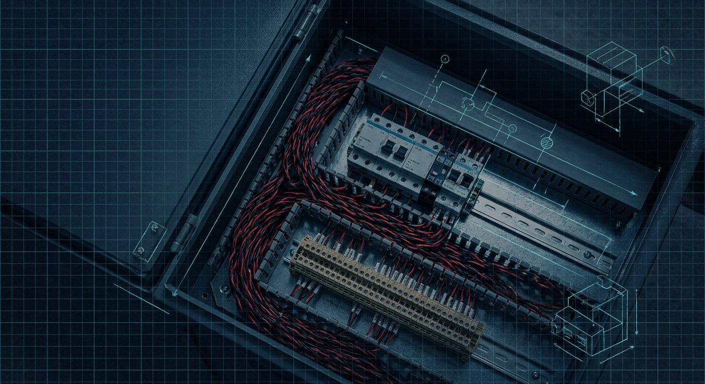
If you open almost any custom machine enclosure built in the last twenty years, you see the same structural bottleneck. Half the usable backplate depth is eaten by 80mm-wide slotted PVC trunking. Running through that ducting are thick bundles of 18 AWG and 22 AWG multi-conductor cables, each jacketed line terminating at a towering row of multi-level terminal blocks.
Every basic analog sensor out on the gantry takes three or four conductors to land: 24V supply, 0V common, a 4-20mA or 0-10V signal core, and a drain wire that has to be tied to a shield grounding bar. If you have forty field sensors, you are running over a hundred individual terminations just to get physical I/O to your PLC slice racks. That wiring takes space, adds weight, drives up cabinet assembly time, and creates dozens of points where a loose ferrule or an overtightened screw cage can fail during factory commissioning.
At SPS 2025 in Nuremberg, component makers like Phoenix Contact, Rockwell Automation, and Weidmüller showed production hardware built around a cleaner alternative: Single Pair Ethernet (SPE) and its process-industry sibling, Ethernet-APL. Instead of running heavy multi-conductor cables and fat RJ45 patch cords, these systems run data and power over a single unshielded or shielded twisted pair of copper wires.
For engineers who build autonomous carts, robotic cells, or custom skid machinery, this transition quietly solves the worst physical constraints of panel design.
The Physical Reality of the Wire Duct Bottleneck
When generalist robotics and mechatronics engineers inherit a control box build, the panel layout is usually an afterthought compared to the mechanical kinematics or the motion control logic. But physical panel real estate dictates enclosure sizing, thermal load, and assembly labor.
A conventional discrete machine architecture relies on point-to-point field wiring routed back to marshalling strips. Consider a standard eight-port pneumatic valve manifold with position feedback sensors, combined with a dozen optical proximity switches, three load cells, and five temperature transmitters.
Under standard 24V wiring rules, the bill of materials for your marshalling zone requires:
- Three-tier DIN rail terminal blocks (power distribution, signal, ground) with a pitch of roughly 5.2mm to 6.2mm per block.
- Dedicated copper ground bars or PE terminal blocks with continuous busbars.
- Massive slotted wire trunking (often 80mm wide by 80mm deep) simply to hold the bend radius and physical volume of jacketed 18/4 and 22/2 cables entering through gland plates.
- PLC remote I/O slice modules (analog input modules, digital sinking/sourcing modules, RTD inputs) taking up thirty to forty centimeters of DIN rail space.
Each conductor requires cutting to length, stripping the outer jacket, stripping individual cores, crimping bootlace ferrules, applying heat-shrink wire labels, and torquing screws or actuating push-in spring clamps. A cabinet with two hundred field termination points can easily burn forty labor hours purely on wire prep and point-to-point continuity checking before the main breaker is ever thrown.
Beyond labor, the bulk creates thermal traps. Thick wire bundles packed tight in plastic trunking block convective airflow across switch-mode power supplies and motor drives. If you need to make a field modification after the machine is built, fishing a new four-conductor cable through packed trunking is miserable work.
How Single Pair Ethernet Works at the Copper Level
Single Pair Ethernet is not a proprietary fieldbus. It is an extension of the IEEE 802.3 standard that collapses the physical layer (PHY) down to two copper conductors while leaving higher-level network stacks like EtherNet/IP, Profinet, Modbus TCP, and OPC UA completely untouched.
Standard office Ethernet (100BASE-TX) uses two twisted pairs (four wires). Gigabit Ethernet (1000BASE-T) uses four twisted pairs (eight wires) terminated into bulky RJ45 jacks. Those RJ45 plugs are notoriously fragile in high-vibration industrial environments, and the thick eight-conductor cables have stiff bend radii that make clean routing inside shallow 150mm or 200mm electrical enclosures difficult.
SPE changes the physical layer standard under several IEEE designations:
IEEE 802.3cg (10BASE-T1L and 10BASE-T1S)
This is the standard that matters most for machine builders and control cabinets.
- 10BASE-T1L provides full-duplex 10 Mbps communication over a single twisted pair up to a distance of 1,000 meters (1 km). It uses point-to-point topology.
- 10BASE-T1S provides 10 Mbps over short distances (up to 25 meters point-to-point, or at least 15 meters in a multi-drop bus configuration connecting up to at least eight nodes on a single pair without active switches).
IEEE 802.3bw (100BASE-T1) and IEEE 802.3bp (1000BASE-T1)
Originally driven by the automotive sector to eliminate vehicle wiring harness weight, these variants deliver 100 Mbps and 1 Gbps over a single pair up to 15 to 40 meters. They are increasingly used in machine vision systems and compact mobile robots where camera data needs to fit through tight cable tracks.
Because 10 Mbps is roughly three orders of magnitude faster than a legacy 4-20mA loop or a 31.25 kbps Foundation Fieldbus connection, it easily carries continuous sensor values, configuration data, and device health metrics simultaneously.
Traditional Ethernet (Cat5e/Cat6)        Single Pair Ethernet (10BASE-T1L)
[ 4 Pairs / 8 Wires ]                     [ 1 Pair / 2 Wires ]
- Bulky RJ45 or M12 D/X-Code              - Compact Push-in or M8/M12 SPE
- Rigid bend radius                       - Highly flexible, thin profile
- Up to 100m distance                     - Up to 1,000m distance
- PoE requires multiple pairs             - PoDL shares the same single pair
Power Over Data Line (PoDL)
Running high-speed data over two wires is only useful if you do not have to pull a separate pair of 24V DC wires to power the sensor. SPE solves this using Power over Data Line (PoDL), standardized under IEEE 802.3bu and IEEE 802.3cg.
PoDL works similarly to standard Power over Ethernet (PoE), but it couples DC power onto the same single pair of copper conductors carrying the high-frequency differential AC data signal. Inductive coupling circuits and low-pass filters at each end separate the DC power rail from the data transceivers.
PoDL defines multiple power classes spanning 12V, 24V, and 48V nominal systems. For industrial machinery, the relevant classes deliver between 10W and 50W of regulated DC power directly to the field transmitter, flowmeter, or valve block.
That means a single two-conductor cable (such as an 18 AWG or 22 AWG shielded pair) entering the cabinet carries everything. You do not need a separate 24V power distribution strip next to the signal terminals. The device powers up and joins the network the moment the two wires are seated.
Shrinking the Control Enclosure
Replacing discrete analog drops with SPE restructuring changes the interior layout of the control cabinet in three major areas.
1. Marshalling Strips Drop Away
In a legacy layout, 60% of your terminal rail is passive marshalling: blocks whose only job is to receive field wires, split off the 24V power, and route the signal wire to a remote I/O slice.
With an SPE architecture, field lines land either directly on high-density SPE DIN rail switch modules or on miniature push-in connector blocks (using standardized industrial SPE interfaces like IEC 63171-2 for IP20 in-cabinet use, or IEC 63171-5 / IEC 63171-6 for IP67 field interfaces).
Because IEC 63171-2 jacks take up less than half the front-panel area of an RJ45 port and do not require three tiers of screw terminals, you can fit 16 or 24 SPE ports on a DIN rail module no wider than a standard eight-channel analog PLC slice.
2. Trunking Volume Falls by Half
An industrial two-conductor SPE cable with shielding has an outer diameter of roughly 4.5mm to 5.5mm, compared to 8mm to 10mm for a ruggedized four-conductor shielded instrumentation cable. Unshielded in-cabinet SPE wiring is thinner still.
When cross-sectional wire bundle areas drop by 50% to 70%, you can downsize internal trunking from 80x80mm to 40x40mm or 30x40mm. This brings the entire backplate layout inward, allowing engineers to pick smaller standard enclosure sizes (for example, stepping down from an 800x600x300mm cabinet to a 600x400x200mm box) or leaving open space for future servo drive expansions.
3. Assembly Labor and Wiring Errors Plunge
Data from industrial OEMs testing in-cabinet SPE solutions indicates wiring time reductions of up to 80% compared to legacy hardwired points.
Stripping two wires instead of four, eliminating separate shield jumpers to ground rails, and using push-in cage clamp connectors reduces manual touch time. More importantly, it removes point-to-point landing errors. If an operator flips the two wires on a standard polarity-insensitive 10BASE-T1L PHY, the auto-polarity correction built into modern transceivers (like the Microchip LAN8670/1/2 or Analog Devices ADIN1100) resolves the connection automatically.
| Attribute | Legacy 4-20mA / Discrete Setup | Standard Industrial Ethernet | Single Pair Ethernet (10BASE-T1L) |
|---|---|---|---|
| Conductor Count | 3 to 5 wires per field device | 4 or 8 wires (2 or 4 pairs) | 2 wires (1 pair) |
| Max Loop Distance | Up to ~1,000m (at low bandwidth) | 100 meters | 1,000 meters |
| Data Bandwidth | 1.2 kbps (HART) to static DC | 100 Mbps / 1 Gbps | 10 Mbps (Full Duplex) |
| Power Delivery | Separate power lines needed | PoE (requires 2 or 4 pairs) | PoDL (over the same single pair) |
| Connector Profile | Bulky screw/spring terminal tiers | RJ45 or M12 D/X-Code | Miniature IEC 63171-2 / M8 SPE |
| Cabinet Wire Volume | High (demands large trunking) | Medium-High (stiff cables) | Minimal (thin, flexible routing) |
Moving Past the 4-20mA Diagnostic Blind Spot
Beyond cabinet dimensions, the biggest operational gain for mechatronics generalists is diagnostic visibility.
When a standard 4-20mA pressure transducer fails or misbehaves on a machine, your PLC analog input card simply reads a raw integer value corresponding to low current. If the sensor wire snaps, you see 0mA (or 3.6mA under NAMUR NE43 fault conditions). If the sensor element is coated in debris or experiencing thermal runaway, the PLC continues to read an analog value between 4mA and 20mA, treating erroneous data as valid process state.
To troubleshoot, an engineer has to open the panel, clip a multimeter across the terminal test points, check loop voltage, or plug in a handheld HART communicator and wait through a slow, clunky polling cycle.
With SPE running down to the sensor housing:
- Native IP Addressing: The sensor is a first-class node on the subnet. You can query its internal web page or read its diagnostic tags straight from your PLC controller tags without an intermediate analog-to-digital conversion module.
- True State Monitoring: The device reports raw process variables alongside secondary measurements. A single flowmeter on an SPE drop transmits mass flow, fluid temperature, totalized volume, diagnostic error codes, optical signal quality, and internal operating hours over its cyclic data frame.
- Zero Re-calibration Offsets: Analog conversion error (DAC inside the sensor to ADC inside the PLC slice) disappears. The numeric float generated by the sensor crystal is the exact numeric float received in the PLC processor memory.
For machine builders writing structured text or ladder logic, this eliminates the tedious rung logic historically required to scale 4-20mA integer counts (0-27648 on Siemens, or 0-32767 on Rockwell) into engineering units.
What About Ethernet-APL?
If you work on skids destined for oil, gas, chemical processing, or hydrogen energy installations, you will see the term Ethernet-APL (Advanced Physical Layer) used alongside SPE.
Ethernet-APL is not a competing standard. It is a specific industrial application profile built on top of IEEE 802.3cg (10BASE-T1L). APL adds explicit intrinsic safety rules (2-WISE, Two-Wire Intrinsically Safe Ethernet) and defines standardized power limits so that 10BASE-T1L cables can run directly into Zone 0, Zone 1, and Class I, Division 1 hazardous explosive atmospheres without adding heavy explosion-proof conduit or external zener barriers inside the control cabinet.
Inside the cabinet, an APL power switch or field switch handles the transition between standard 4-pair Industrial Ethernet (running to your safety PLC or SCADA) and the single-pair field drops running out to process transmitters. The result is the same: massive racks of intrinsic safety barriers and marshalling terminal blocks are replaced by a single DIN rail rail-mounted switch.
Practical Design Considerations for Your Next Build
If you are planning your next machine build or redesigning an existing control enclosure to take advantage of SPE, keep several engineering details in mind.
Choose Your Topology Realistically
While 10BASE-T1S supports multi-drop bus lines (daisy-chaining multiple sensors along one pair like an RS-485 bus), most industrial installations favor point-to-point star topologies using 10BASE-T1L switches. Star topologies make fault isolation trivial: if a single sensor wire gets severed by a pinch point on a robotic axis, only that single node drops offline, leaving the rest of the machine network running.
Watch Your Connector Selection
Do not specify standard RJ45 connectors adapted to single pair cables inside a panel. Use connectors built for the standard. IEC 63171-2 connectors provide locking push-pull mechanisms designed specifically for high-density IP20 DIN rail devices. For field drops exiting the enclosure, specify M8 or M12 SPE connectors rated to IP67 to prevent moisture ingress.
Grounding and Shielding Still Matter
Although differential signaling on a twisted pair provides solid common-mode noise rejection, high-current PWM cables from variable frequency drives (VFDs) and servo motors will still couple high-frequency EMI onto unshielded data lines. When routing SPE lines alongside motor cables in tight gantry tracks, use shielded single pair cables (STP) and ensure the shield lands cleanly on the metallic housing of your SPE switch or enclosure entry plate.
Network Subnet Planning
When every sensor has its own MAC address and IP address, your network device count scales rapidly. A machine that previously had one PLC, two drives, and an HMI (4 IP addresses) might suddenly have 60 networked nodes once flowmeters, position sensors, and valve blocks sit on SPE.
Make sure your network architecture uses managed switches with DHCP option 82 or clear subnetting rules so maintenance technicians can swap a failed sensor without having to manually assign static IPs through a laptop in the field.
Tools that assist in mapping panel topologies and synthesizing wiring schematics, including platforms like LabCD (labcd.ai) for control system layout, help catch these address overlaps, terminal allocations, and power consumption limits early in the design cycle before backplates are drilled.
Where to Start
SPE is no longer a laboratory concept. With transceivers from Microchip and Analog Devices shipping in volume, and automation vendors releasing native SPE switches, sensor blocks, and I/O couplers, the hardware is ready for production machines.
If you want to test the water without redesigning an entire machine line, start with a modular sub-assembly. Pick a valve island bank or a remote sensor-dense gantry on an upcoming build. Replace the 25-conductor multi-drop cable and its associated DIN rail terminal cluster with a single pair Ethernet drop and an IP67 field hub.
Measure the time it takes your shop floor to wire that section, look at the space you get back inside the enclosure, and check how much faster your diagnostic routines pull error states from the devices. You will quickly realize that the days of packing massive wire ducts with multi-conductor cable are coming to a well-deserved close.
Sources
- https://www.single-pair-ethernet.com/en
- https://www.microchip.com/en-us/products/interface-networking-connectivity/ethernet/single-pair-ethernet
- https://www.phoenixcontact.com/en-pc/technologies/single-pair-ethernet
- https://www.industrialsolutionsnetwork.com/cesburley/resources/simplifying-in-cabinet-connectivity-with-ethernet-ip
- https://industrialethernet.net/technology/industrial-ethernet/single-pair-ethernet-and-ethernet-apl-moving-ahead/
- https://www.mouser.com/blog/understanding-single-pair-ethernet-for-industrial-automation