Nauticus Robotics secured up to $50 million in financing to build an autonomous marine robotics manufacturing and service base in the United Arab Emirates. For years, subsea intervention in the Arabian Gulf has meant importing hydraulic work-class remotely operated vehicles from Houston, Aberdeen, or Norway, flying in specialist crews, and running massive surface support vessels burning tens of tons of marine diesel a day.
Putting an assembly and production plant in the UAE flips that model. Nauticus builds the Aquanaut, an untethered, all-electric subsea autonomous robot, along with the Olympic Arm, an electric manipulator designed for deepwater intervention. Assembling these vehicles locally is a deliberate play for regional offshore energy contracts, driven by In-Country Value (ICV) requirements in Abu Dhabi and IKTVA benchmarks across the border in Saudi Arabia.
For machine shops, fabrication yards, and mechanism designers in Mussafah, Dubai Industrial City, and the Eastern Province, this investment is a tangible procurement target. It is also an unforgiving technical barrier. Building electric subsea arms and pressure hulls is nothing like machining downhole drill collars or API 6A high-pressure pipeline flanges. The mechanical bill of materials for an all-electric subsea robot operates under a completely different set of structural, tribological, and sealing constraints.
The Mechanical Bill of Materials for All-Electric Manipulators
Traditional subsea manipulators, like the Schilling Titan 4, run on hydraulics. Hydraulic arms are brute-force systems. They use high-pressure mineral oil driven by an onboard hydraulic power unit, switched through solenoid valves, and piped via flexible hoses to linear cylinders or rotary actuators. They tolerate loose mechanical tolerances because oil pressure compensates for internal leakage, and external seawater is held at bay by keeping the entire hydraulic loop slightly over-pressured relative to ambient depth.
An all-electric manipulator like the Olympic Arm abandons hydraulic hoses entirely. Every joint houses a dedicated electric actuator, a high-ratio gearset, position sensors, motor drive electronics, and mechanical brakes, all packaged inside a sealed, pressure-rated envelope.
+-------------------------------------------------------------------------+
|                        SUBSEA JOINT ARCHITECTURE                        |
|                                                                         |
|  +------------------+   +-------------------+   +--------------------+  |
|  | Frameless BLDC   |-->| Strain Wave /     |-->| Output Hub & Dual  |  |
|  | Stator & Rotor   |   | Planetary Gearset |   | Dynamic Face Seals |  |
|  +------------------+   +-------------------+   +--------------------+  |
|           |                       |                       |             |
|           +-----------+-----------+-----------+-----------+             |
|                       |                       |                         |
|              +-----------------+     +-----------------+                |
|              | Dielectric Oil  |     | 1-bar Dry Cavity|                |
|              | Compensated (P) |  OR | Ti-6Al-4V Shell |                |
|              +-----------------+     +-----------------+                |
+-------------------------------------------------------------------------+
The typical bill of materials for one rotary joint in an electric subsea arm breaks down into five critical hardware groups:
- Structural shell and link brackets: Grade 5 Titanium (Ti-6Al-4V) or hard-anodized 7075-T6 aluminum for shallow assets, transitioning to Super Duplex stainless steel (UNS S32750) when raw mass is needed for ballast balance.
- Gearing and transmission: Strain-wave gearsets (typically customized component sets without standard housings) or multi-stage planetary drives with custom output bearings capable of taking combined radial and axial thrust loads up to 15 kN.
- Actuation: Frameless brushless torque motors (rotor bonded directly to the input shaft, stator shrunk-fit into the structural housing).
- Sealing systems: Spring-energized PTFE dynamic rotary lip seals, dual static FKM/Viton O-rings with PTFE back-up rings, and custom rotary shaft sleeves coated with tungsten carbide.
- Fasteners and hardware: Nitronic 50 or 60 high-strength stainless steel bolts, treated to prevent galling against titanium internal threads.
Every single gram of material and every micrometer of tolerance in that stack serves two masters: preventing seawater ingress under 100 to 300 bar of external hydrostatic pressure, and dissipating motor heat without the luxury of active airflow.
Pressure Vessel Design: 1-Bar Enclosures vs. Oil-Filled Compensation
When designing subsea robotic sub-assemblies, you face a fundamental mechanical fork in the road. You either build a 1-bar dry enclosure that resists external collapse, or you flood the housing with dielectric fluid and equalize the internal pressure to match the surrounding sea.
Both approaches exist on the Aquanaut and its manipulator arms, and both impose brutal requirements on local CNC shops.
1-Bar Structural Housings
For central electronics, inertial navigation units, and optical camera payloads, the housing must remain at 1 atmosphere internal pressure. At 3,000 meters depth, seawater exerts roughly 30 MPa (4,350 psi) of crushing pressure on the outside walls. In the shallow waters of the Arabian Gulf (typically 30 to 80 meters depth), ambient pressure is lower (4 to 9 bar), but vehicles intended for global deployment must be qualified for deepwater intervention.
Critical Buckling Pressure Formula for Cylindrical Shells:

P_cr = (2 * E / (1 - v^2)) * (t / D_o)^3

Where:
  E   = Young's Modulus (Ti-6Al-4V: ~114 GPa)
  v   = Poisson's Ratio (~0.34)
  t   = Wall thickness
  D_o = Outer diameter
Designing these shells is not just a yield-strength calculation. Thin-walled cylinders under external pressure fail by elastic buckling long before the material reaches its yield point.
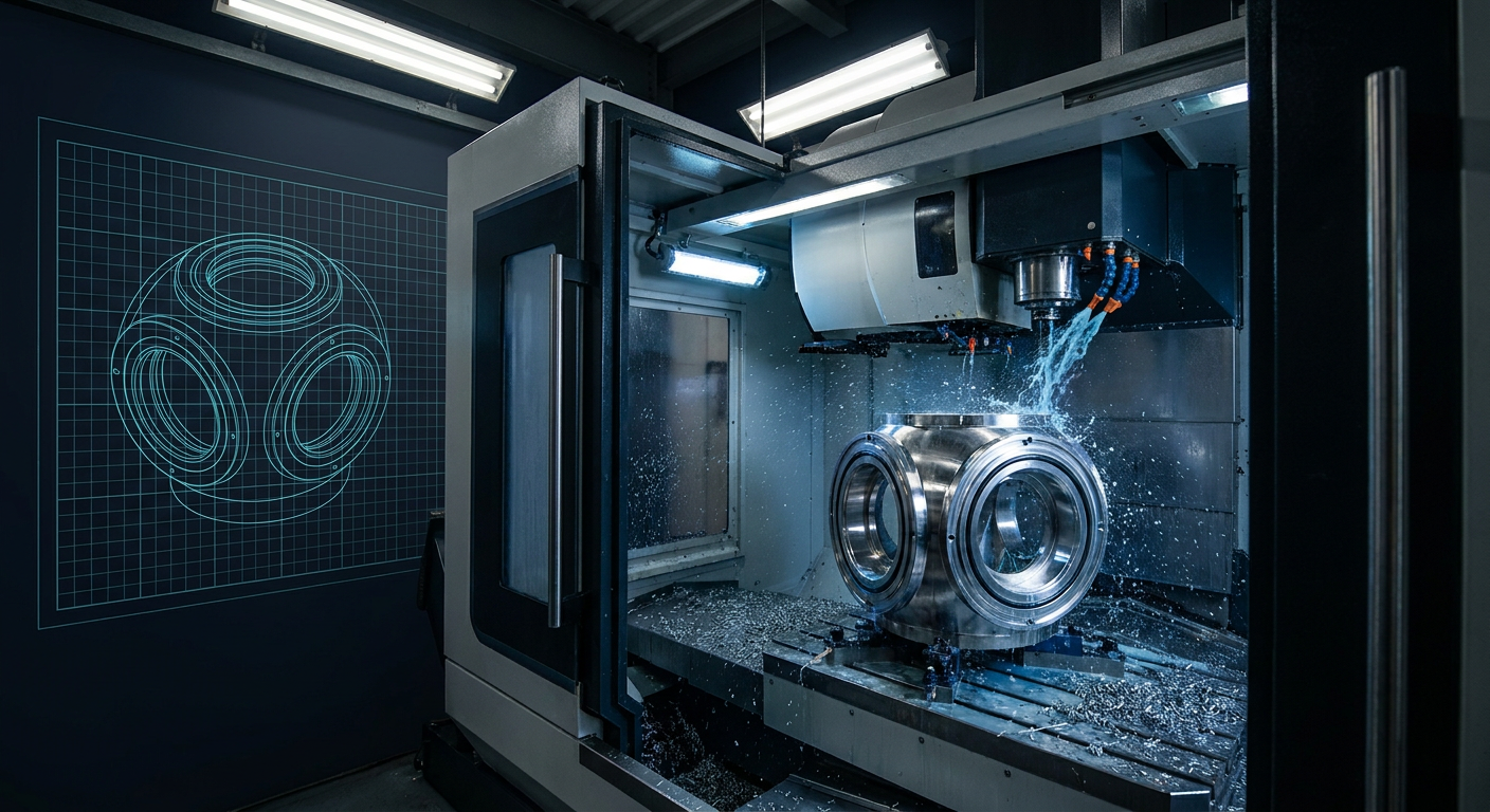
To survive, the machine shop must turn Grade 5 titanium cylinders with extreme geometric concentricity. If a shop turns a 200 mm outer diameter titanium pressure hull with a 6 mm wall thickness, an out-of-roundness of just 0.08 mm drops the critical buckling pressure by up to 30 percent. The shop cannot simply rough out a cylinder, flip it in a three-jaw chuck, and finish-bore the inside.
Titanium retains high residual stresses. As you bore out the internal core, the tube moves. Local suppliers taking on these hulls will need multi-axis mill-turn centers, custom expanding mandrels, and stress-relieving cycles between roughing and finishing passes to keep circularity within 0.015 mm over a 600 mm length.
Pressure-Compensated Wet Enclosures
For high-power joint actuators, building thick titanium 1-bar shells creates an unmanageable mass penalty. The arm becomes too heavy to lift its own payload. The standard solution is pressure compensation.
The motor, gearset, and encoder are submerged in an incompressible dielectric oil (such as synthetic hydrocarbon or fluorinated oils). A flexible elastomeric bladder or a spring-loaded piston compensator connects the oil reservoir to the outside seawater. As the robot dives, external pressure pushes on the bladder, equalizing the internal fluid pressure to the ambient sea pressure. The differential pressure across the housing walls drops to near zero.
Pressure compensation solves the wall-thickness problem, but it creates two new mechanical headaches:
- Viscous drag on the rotor: Spinning a high-speed motor inside thick dielectric oil causes significant drag losses. Motor designers have to run low-kV, high-pole-count frameless motors at lower RPMs, forcing higher gear reduction ratios.
- Fluid contamination and particulate traps: Gear wear generates microscopic metallic debris. In a closed oil-compensated cavity, that debris flows directly into the motor air gap. Housings require integrated magnetic traps and internal labyrinth channels machined into the fluid path to pull iron particles out of suspension before they bridge the 0.3 mm stator-rotor clearance.
Sealing Interfaces and Surface Finish Realities
If you ask a subsea robotics engineer where their systems fail, the answer is almost never structural fracture. It is seal failure.
Static seals (sealing endcaps to main barrels) are relatively straightforward: standard radial or face O-ring grooves. Yet even here, typical commercial machining practices fall short. Subsea O-ring grooves require continuous toolpaths without dwell marks. A single tool retract mark across an O-ring sealing face creates a micro-channel that helium leak testers will detect instantly.
Dynamic seals on rotating joint shafts are where Gulf machine shops will face their steepest learning curve.
+-------------------------------------------------------------------------+
|                   DYNAMIC SHAFT SEAL LAND TOLERANCES                    |
|                                                                         |
|  Shaft Surface Finish:     Ra 0.10 to 0.20 um (4 to 8 uin)              |
|                            Rz < 1.0 um                                  |
|                            Rmr > 70% at 0.5 * Rz depth (Plunge ground)  |
|  Shaft Runout (TIR):       < 0.010 mm total indicator reading           |
|  Housing Bore Finish:      Ra 0.40 um (16 uin)                          |
|  Seal Type:                PTFE C-Cap / Elastomer-Energized Lip Seal   |
+-------------------------------------------------------------------------+
A dynamic shaft seal running in seawater must keep abrasive suspended sand, silt, and salt ions out while holding dielectric fluid in. Standard elastomeric lip seals will fail within 50 hours of continuous subsea joint rotation because fine particulate embeds in the elastomer and scores the shaft.
Subsea robotic actuators rely on spring-energized PTFE seals (such as cantilever spring-loaded Turcon or Omniseal rings). These seals require a shaft surface finish of Ra 0.1 to 0.2 µm (4 to 8 microinches).
Achieving that finish requires cylindrical plunge grinding followed by micro-polishing or roller burnishing. You cannot achieve it with standard CNC turning inserts, no matter how small the feed rate.
Furthermore, the grinding must be plunge grinding without lead lines. If the grinding wheel moves axially across the shaft during finishing, it leaves microscopic spiral grooves on the surface. When the robot joint rotates, those spiral grooves act as an Archimedes screw, pumping seawater past the seal lips and flooding the actuator cavity.
Local shops bidding on shaft manufacturing will need dedicated cylindrical grinding machinery with diamond-dressed wheels and optical surface profilometers capable of measuring Rz, Rpk, and material ratio curves (Abbott-Firestone curves), not just basic Ra numbers.
Exotic Metallurgy: Machining Without Scrapping the Part
Subsea robots live in a galvanic soup. Putting 6061 aluminum in direct electrical contact with 316 stainless steel in warm Arabian Gulf seawater (where surface temperatures hit 36°C and salinity exceeds 40 PSU) creates a rapid galvanic corrosion cell that eats the aluminum within months.
Nauticus systems rely heavily on titanium, nickel-based alloys, and specialized stainless steels. These materials are notoriously difficult to cut.
+-----------------------------------------------------------------------------+
|                        SUBSEA MATERIAL MACHINING MATRIX                     |
+-------------------+--------------------+------------------+-----------------+
| Material          | Primary Subsea Use | Machinability    | Major Machining |
|                   |                    | Rating (AISI 100)| Risk Factor     |
+-------------------+--------------------+------------------+-----------------+
| Ti-6Al-4V (Gr. 5) | Pressure housings, | 22%              | Tool galling,   |
|                   | structural links   |                  | work hardening  |
+-------------------+--------------------+------------------+-----------------+
| Nitronic 60       | Dynamic shafts,    | 28%              | High shear load,|
| (UNS S21800)      | anti-galling bolts |                  | chip bird-nests |
+-------------------+--------------------+------------------+-----------------+
| Super Duplex      | High-load pins,    | 30%              | Built-up edge,  |
| (UNS S32750)      | structural hubs    |                  | high heat       |
+-------------------+--------------------+------------------+-----------------+
| Al 7075-T6        | Internal chassis,  | 70%              | Stress warp,    |
| (Hard Anodized)   | shallow brackets   |                  | galvanic risk   |
+-------------------+--------------------+------------------+-----------------+
Grade 5 Titanium (Ti-6Al-4V)
Titanium has poor thermal conductivity (roughly 6.7 W/m·K compared to 167 W/m·K for aluminum). When milling titanium link brackets, heat does not disperse into the chips; it concentrates entirely at the cutting edge of the carbide insert.
Without high-pressure through-spindle coolant (at least 70 bar) directly targeting the cutting zone, carbide inserts experience severe thermal shock and micro-chipping. Speeds must stay low (typically 40 to 60 m/min with standard PVD coated carbide), and feed per tooth must remain aggressive enough to prevent rubbing and work hardening.
When optimizing bracket mass and pocket geometry, design tools like Mexaio AI can help generate internal rib structures that maintain stiffness under structural torque while stripping out unnecessary material. But if those generated ribs are too thin, say under 1.5 mm over a 100 mm depth, tool chatter during machining will ruin the wall thickness tolerance.
Nitronic 60 (UNS S21800)
Subsea fasteners and threaded interfaces face severe galling risks. When a titanium bolt is torqued into a titanium housing without a barrier, the oxide layer shears off and the two parts cold-weld together. Once seized, the bolt cannot be removed without EDM drilling the entire housing out.
To prevent this, subsea mechanical designs use Nitronic 60 for bolts, threaded inserts, and sliding shafts. Nitronic 60 is an austenitic stainless steel alloyed with silicon and manganese specifically to prevent galling and wear.
Machining it is a nightmare. It produces stringy, tough chips that wrap around the tool holder and work-hardens instantly if the tool dwells for even half a second. Machinists must maintain positive rake angles, sharp cutting edges, and uninterrupted feeds.
The Qualification Gap: What Local Shops Must Fix
Winning a supplier contract from an OEM like Nauticus is not just a matter of owning a 5-axis Mazak or DMG Mori. Most precision machine shops in the UAE and Saudi Arabia are tuned to the API (American Petroleum Institute) ecosystem: API 5CT casing threads, API 6A valves, API 16D blowout preventer parts.
Robotics manufacturing runs on aerospace and specialized subsea qualification standards:
- Quality Management: Transitioning from ISO 9001 to AS9100 Rev D. Subsea autonomous systems demand full material traceability down to the raw billet melt mill certificate, including Charpy impact testing and ultrasonic grain structure validation.
- Hydrostatic Pressure Testing: Shops must have access to certified hyperbaric test chambers. A pressure housing cannot be shipped based on CMM inspection alone. It must undergo 1.5x working depth hyperbaric cycling (holding at test pressure for multiple hours, venting, and repeating for 3 to 5 cycles) followed by immediate internal inspection for moisture ingress.
- Helium Mass Spectrometry: To detect micro-porosity in raw billet material and seal interfaces, components must pass vacuum helium leak testing down to $1 \times 10^{-8} \text{ mbar}\cdot\text{l/s}$. Liquid dye-penetrant testing is not sufficient for high-pressure subsea electronic dry cavities.
- Cleanliness Standards: Assembling an oil-compensated electric joint requires particulate-free cleanrooms. A single metallic chip left inside a housing will ground out a 300V motor stator or jam a strain-wave gear teeth mesh.
+-------------------------------------------------------------------------+
|                   SUPPLIER CAPABILITY GAP ANALYSIS                      |
|                                                                         |
|  Capability                 Typical Gulf Shop    Subsea Robotics Spec   |
|  ------------------------   ------------------   --------------------   |
|  CMM Traceability           3-Axis Standard      5-Axis Scanning + Form |
|  Surface Roughness Checks   Ra Only              Ra, Rz, Rmr (Bearing)  |
|  Coolant Delivery           Flood (Low P)        Through-Tool > 70 bar  |
|  Pressure Testing           Hydrostatic (Water)  Hyperbaric Chamber     |
|  Leak Detection             Dye Penetrant        Helium Mass Spec       |
|  Cleanliness Assembly       Open Shop Floor      ISO Class 7 Cleanroom  |
+-------------------------------------------------------------------------+
What to Watch and How to Prepare
The $50 million Nauticus hub is not an isolated initiative. It signals a structural shift in how Gulf offshore assets will be maintained. ADNOC, Saudi Aramco, and regional offshore operators are pushing aggressively to lower the carbon intensity of subsea field operations. Replacing 80-meter diesel-burning ROV support vessels with autonomous electric systems like Aquanaut directly hits those ESG targets.
For machine shop owners, contract manufacturers, and tooling engineers in the region, the path forward requires deliberate operational upgrades:
- Audit your finishing setup. If your shop cannot grind dynamic seal shafts to Ra 0.2 µm without spiral lead lines, invest in micro-finishing attachments and optical surface roughness gauges now.
- Review your titanium machining parameters. Dial in high-pressure through-spindle coolant processes and rigid fixturing designed to avoid thin-wall chatter on thin titanium shells.
- Build hyperbaric testing partnerships. If your facility cannot afford a 300-bar hyperbaric pressure vessel, form testing consortiums with local universities (like Khalifa University or KFUPM) or regional marine research labs to qualify parts locally.
- Clean up the assembly loop. Establish dedicated, enclosed clean-assembly bays isolated from the heavy grinding and welding dust common in general oilfield yards.
The work is coming to the Gulf. The suppliers who win the purchase orders will not be the ones who quote the lowest price, but the ones whose parts seal the first time they hit 300 bar.