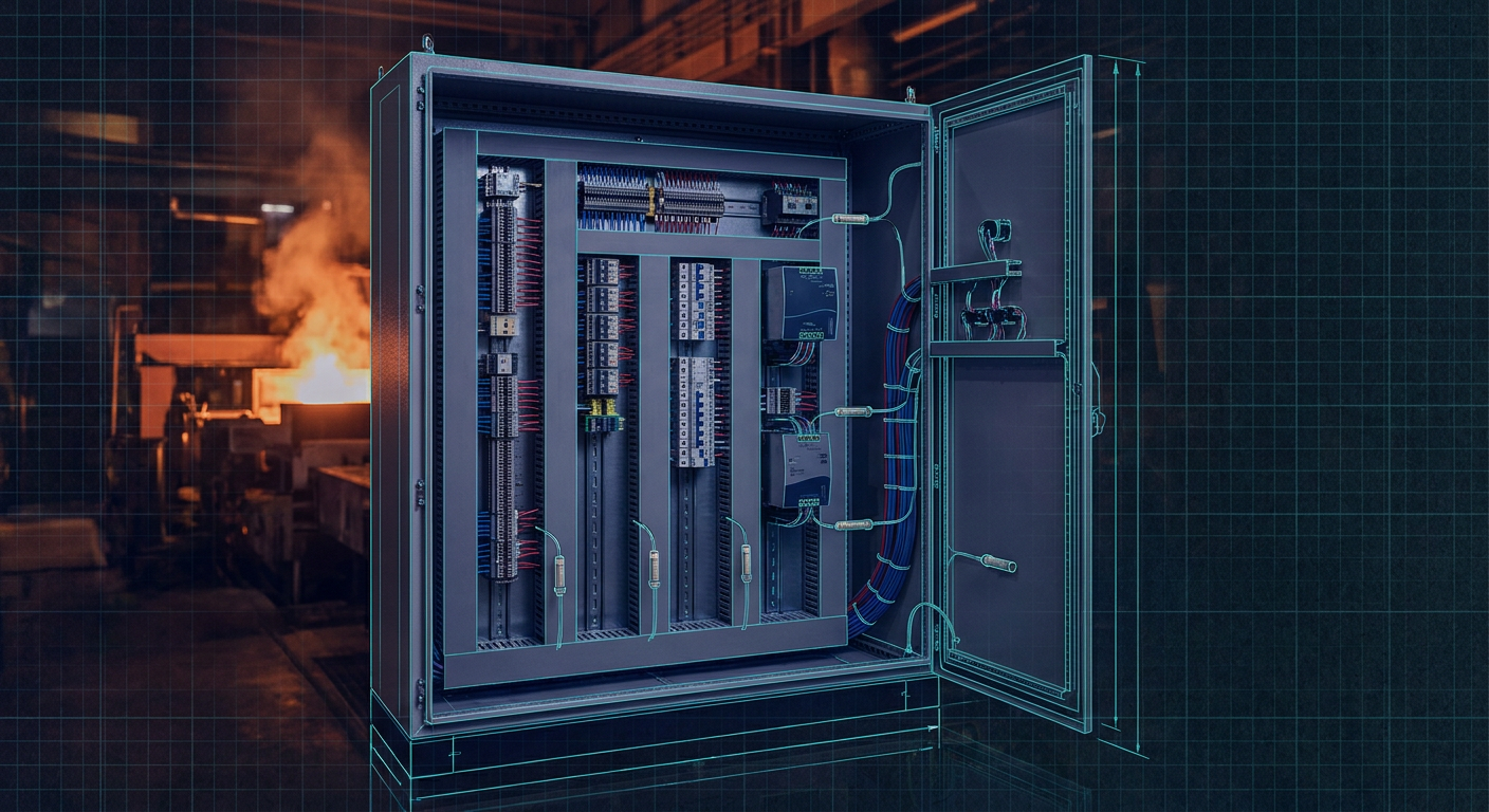
If you build a robotics skid or an automated test cell in an air-conditioned shop, the control box usually behaves itself. You lay out your 35mm DIN rails, snap in a 24V DC power supply, drop your PLC and motor drives next to it, run wires through slotted trunking, and close the door. On the bench at 21°C, everything runs cool.
Then you ship that exact enclosure to an outdoor site or an unconditioned plant floor in Abu Dhabi or Jubail in July.
Around 2:00 PM on the third day of commissioning, your PLC reboots without an error log. Or a safety relay drops out intermittently, killing a conveyor. You open the enclosure door, and a wall of 65°C heat hits your face. When you put a multimeter on the 24V bus, the voltage has collapsed to 18V because the power supply went into thermal foldback.
Most robotics and mechatronics engineers inherit the job of control panel layout without ever being taught panel thermal design. Standard CAD tools let you place components edge-to-edge as long as the 3D bounding boxes do not collide. But packing a DIN rail like a luggage rack is a recipe for silent, intermittent field failures when the ambient air climbs past 40°C.
Here is how to calculate the real thermal budget inside a high-ambient control cabinet, size your DC supplies without guessing, and pick a cooling method that does not ruin your hardware.
The Real Internal Temperature of a Sealed Box
To understand why components fail in the summer, you have to separate ambient temperature from enclosure internal temperature. Ambient is the air outside the box. Internal temperature is what your electronics actually breathe.
Consider an unshaded, painted mild-steel enclosure mounted outdoors in an environment where peak ambient air reaches 48°C.
Solar radiation on the roof and sidewalls can add an effective heat flux of 500 to 1000 Watts per square meter of exposed surface. That solar load alone can raise the enclosure skin temperature 10°C to 15°C above the surrounding air before you even switch on the main breaker.
Inside the box, every component turns a percentage of its operating power into pure heat:
- Switch-mode power supplies lose 8% to 15% of their total throughput as heat.
- Variable frequency drives (VFDs) and servo drives lose roughly 2% to 4% of their connected motor load in drive switching losses.
- PLC racks, communication gateways, and embedded compute blocks consume and radiate 15W to 50W continuously.
- Relay coils, contactors, fuses, and terminal blocks each bleed a few watts continuously across their internal resistance and coil windings.
If your internal components dump a combined 250W of waste heat inside a sealed 800mm by 600mm by 300mm NEMA 4 enclosure, natural surface convection can only shed a fraction of that heat. Without active cooling, the internal cabinet air temperature will easily climb 20°C above the outside ambient.
In a 48°C Gulf afternoon, your internal cabinet temperature is sitting at 68°C.
Almost no commercial automation hardware is rated to deliver full performance at 68°C.
Reading the Power Supply Derating Curve
A typical 24V DC, 10-amp (240W) DIN rail switch-mode power supply is advertised as a 10A unit. Many engineers assume they have 10 amps available across the entire operational range listed on page one of the datasheet (often -25°C to +70°C).
If you flip to the back pages of the datasheet, you will find the derating curve. Almost every standard industrial power supply follows a derating profile shaped like this:
- Full 100% rated output current from -25°C up to 45°C or 50°C.
- Linear derating of 2.5% per degree Celsius above 50°C.
- Maximum allowable operating point at 70°C, where output is capped at 50% capacity (5 amps).
Some budget supplies start derating at 40°C. If your internal cabinet temperature reaches 65°C, that 10A supply can safely deliver only 6.25 amps. If your continuous load is 7.5 amps (sensors, valves, PLC modules, safety circuits), the supply will overheat, degrade its internal electrolytic capacitors, or trip its internal thermal protection and shut off the 24V bus.
Effective Capacity = Rated Current * [ 1 - (Internal Temp - Derating Start Temp) * Derating Slope ]
For an ambient of 65°C on a supply that derates at 2.5%/°C above 50°C:
Effective Capacity = 10A * [ 1 - (65 - 50) * 0.025 ]
Effective Capacity = 10A * [ 1 - 0.375 ] = 6.25A
If you size your power supply for 80% continuous bench load (8A on a 10A unit), you are already in danger the second the box runs in a hot environment. You must either double the rated capacity of the supply, split your loads across multiple supplies, or cool the enclosure.
The Chimney Effect on DIN Rails
Switch-mode power supplies rely on natural convection to pull cool air through bottom vents and exhaust hot air out top vents. They do not have internal fans. They need clearance.
If you look at the installation manual for a Phoenix Contact Quint, a Weidmüller PROtop, or a Mean Well NDR supply, they all specify minimum clearance distances:
- 40mm to 50mm of open space above and below the supply.
- 5mm to 15mm of lateral clearance between the supply and neighboring active devices.
In practice, engineers often butt the power supply directly against a row of circuit breakers on the left and a PLC rack on the right to save DIN rail width. This blocks lateral heat radiation and creates a trapped column of stagnant hot air right around the power supply heatsink. The internal thermistor reads an artificial 75°C hot spot, and the supply shuts down even if the average cabinet air is cooler.
Always maintain a hard minimum of 30mm vertical clearance from the top of the supply to the base of the wire duct. Use a wider duct or route cables around the supply rather than stacking the duct right against the vent slots.
The Overlooked Victims: Breakers, Fuses, and Terminals
Power supplies are not the only parts that choke in high ambient temperatures. Thermal-magnetic miniature circuit breakers (MCCBs and MCBs) are calibrated to trip at standard base temperatures, typically 30°C or 40°C.
A thermal breaker works using a bimetallic strip that bends as current heats it up. If the air inside your cabinet is already 60°C, the bimetal strip is pre-heated. It takes far less current to bend that strip and trip the breaker.
A standard 10A C-curve breaker installed in a 60°C cabinet might trip at 8.2A to 8.8A of continuous load. If you run a motor or heater near its nominal rating, you will see nuisance tripping that looks like an electrical fault but is purely ambient heat.
Terminal Block Hot Bars
When you wire high-density IO, it is tempting to snap fifty 2.5mm² push-in or screw terminal blocks tightly together in a continuous block.
If that terminal strip carries power distribution for high-current field devices, every individual terminal has a contact resistance of a few milliohms. At 5A to 10A per point, twenty terminals sitting side by side act like a small heating element. Because they are pressed flat against one another, heat cannot dissipate from the center blocks.
Over months of operation, this localized heating causes plastic embrittlement, loosens screw clamps as metal expands and contracts, and can eventually melt the terminal housings.
Insert partition plates or 5mm end stops every 8 to 10 high-current terminals to create small air gaps and interrupt conductive heat transfer along the rail.
Selecting Enclosure Cooling: Three Practical Paths
Once you calculate your heat load and realize passive metal radiation will not keep your internal temperatures below the derating threshold, you have to choose a cooling strategy. There is no universal solution, only trade-offs involving maintenance, air quality, and cost.
| Cooling Method | Best Suited For | Main Limitation | Typical Maintenance | | :--- | :--- | :--- | :--- | :--- | | Filtered Fans & Louvers | Clean, climate-controlled indoor spaces | Cannot cool below ambient; introduces dust and humidity | Monthly filter pad washing or replacement | | Vortex Coolers | Hazardous locations (ATEX/IECEx), washdown areas, high-vibration skids | High continuous compressed air consumption | Filter drain checks, zero moving parts | | Closed-Loop AC Units | Outdoor panels, sealed NEMA 4/4X boxes, heavy industrial plants | High upfront cost; external coils foul in dirty environments | Condenser coil cleaning, condensate drain clearing |
1. Filtered Fans and Louvers
Fan-and-filter systems are cheap, easy to install, and provide massive airflow for low upfront cost. A pair of 150 CFM fans can drop your internal temperature rise to within 5°C of the outside air.
The critical limitation: fans can never cool the inside of a cabinet below the outside ambient temperature. If the factory floor is 45°C, your cabinet air will be 50°C at best.
More importantly, forced ventilation breaks your enclosure seal. Even with fine filter mats, fine dust, oil mist, and humidity will enter the enclosure. In desert environments, fine sand particles will bypass standard filter media over time, settling on circuit boards and creating conductive paths when humidity rises at night. If you use fans, you must commit to a rigid maintenance schedule to clean or replace filter mats.
2. Vortex Coolers
Vortex coolers convert standard plant compressed air into two streams: one hot exhaust stream and one cold supply stream dropping down into the cabinet. They contain zero moving parts, require no electricity, and are naturally explosion-proof.
They are exceptional for small, sealed, high-vibration control boxes on drilling rigs or mobile robotic machinery where you cannot mount a heavy refrigeration compressor. A vortex cooler also maintains a slight positive pressure inside the enclosure, keeping dust out.
The catch is the operating cost. A small vortex cooler consuming 25 to 35 standard cubic feet per minute (SCFM) of compressed air at 6 bar requires a 7.5 kW compressor running continuously to supply it. Over a year of continuous production, the electricity bill to run that air compressor will dwarf the cost of an air conditioner. Use vortex coolers for localized hot spot relief or harsh hazardous areas, not as a default cooling method for large panels.
3. Closed-Loop Enclosure Air Conditioners
For outdoor panels in high-temperature regions, closed-loop air conditioning is usually the only workable choice.
A closed-loop unit uses two separate air paths. The internal loop pulls hot air from the top of the cabinet, passes it across a cold evaporator coil, and blows cool air back into the bottom of the enclosure. The external loop pulls ambient air across the hot condenser coil and exhausts it outside. The cabinet remains hermetically sealed against dust, sand, and moisture.
When sizing an enclosure air conditioner, follow this basic heat balance:
Required Cooling Capacity (Watts) = Internal Heat Dissipation (Watts) + Solar / Ambient Transmission Load (Watts)
To calculate the solar and ambient transmission load across the enclosure walls:
Q_trans = Area (m²) * Heat Transfer Coefficient (W/m²·K) * (Max Ambient Temp - Desired Internal Temp)
For painted steel, the heat transfer coefficient is roughly 5.5 W/m²·K. For stainless steel, use 4.5 W/m²·K.
If you have a steel cabinet with 4 square meters of exposed surface, max outdoor ambient of 50°C, and a target internal temperature of 35°C:
Q_trans = 4 m² * 5.5 W/m²·K * (50°C - 35°C) = 330 Watts
If your internal electrical components generate 300W of waste heat, your total required cooling load is:
Total Cooling = 300W + 330W = 630 Watts (~2150 BTU/hr)
Always add a 20% safety margin to account for condenser degradation and extreme peak sun exposure. In this case, select an AC unit rated for at least 750W (2560 BTU/hr) at a 50°C ambient rating.
Be careful when checking AC unit ratings. An air conditioner rated for 1000W at 35°C ambient might only provide 700W when the outside ambient hits 50°C because the compressor head pressure rises and cooling efficiency drops.
Practical Layout Rules for Non-Panel Specialists
If you are designing a control box for an automated cell or mobile robot, you do not need full thermal simulation software to build a reliable cabinet. You just need to follow five layout habits that account for real-world thermodynamics.
+-------------------------------------------------------------+
|  [ WIRING DUCT ]                                            |
|                                                             |
|  (Top Rail - Highest Heat Tolerance)                        |
|  [ Terminal Blocks ]   [ Small Relays ]   [ Fuses ]         |
|                                                             |
|  [ WIRING DUCT ]                                            |
|                                                             |
|  (Middle Rail - Sensitive Electronics)                      |
|  [ PLC CPU ]   [ Safety Controller ]   [ Ethernet Switch ]  |
|                                                             |
|  [ WIRING DUCT ]                                            |
|                                                             |
|  (Bottom Rail - Major Heat Sources + Direct Convection)     |
|  [ 24V Power Supply ] <--- 30mm Spacing ---> [ Motor Drive ]|
|                                                             |
|  [ WIRING DUCT ]                                            |
+-------------------------------------------------------------+
First, put your major heat sources at the bottom or near the exhaust air path. Hot air rises. If you put your 24V power supply and servo drives on the bottom DIN rail, make sure there is open vertical space above them so heat can escape without passing directly through the PLC or safety controller above it. If you have an active AC unit blowing cold air down, position the cold air outlet so it feeds the intake vents of your power supplies and drives directly.
Second, never mount heat-generating components directly side-by-side. Leave at least 20mm of empty DIN rail space between a power supply and neighboring circuit breakers or terminal blocks. Use plastic DIN rail spacers (end stops) to enforce this gap physically so assembly technicians do not shove components together to save space.
Third, calculate your DC bus load at the derated temperature, not at nominal 25°C. If your system requires 8A of continuous 24V power, do not specify an 8A or 10A supply for a hot box. Specify a 15A or 20A supply, or split the architecture into two 10A units: one for IO and sensors, one for actuators and coils.
Fourth, treat wire ducts as thermal barriers. Deep, narrow wiring ducts packed full of cables prevent air circulation across the backplate. Leave at least a 25mm air gap between the top of your components and the edge of the wire duct to let convective air currents circulate.
Fifth, pay attention to wire gauge derating inside hot ducts. High ambient temperatures degrade wire insulation ratings. A copper wire carrying 10A that runs safely at 30°C will run significantly hotter when bundled inside a tight wiring trunking with thirty other live conductors in a 55°C cabinet. Step up your wire gauge on main DC power feeds from 1.5mm² (16 AWG) to 2.5mm² (14 AWG) to reduce resistive voltage drops and prevent wire self-heating.
In our internal design flows with LabCD, we treat thermal clearance constraints as hard physical rules during automated schematic synthesis and backplate routing, precisely because catching these issues on a test bench after metal is cut and wired is twice as expensive.
What to Verify on Your Next Build
Before you sign off on a control box layout for an environment that experiences high ambient temperatures, pull the datasheets for your three largest electrical loads: your primary DC power supply, your motor drives, and your main incoming breaker.
Check their derating curves at 55°C internal cabinet temperature. Add up the derated continuous current capacities and verify that they exceed your peak continuous operating loads with at least a 20% margin.
When you power up your first prototype panel on the bench, do not just check logic states and motor rotation. Close the cabinet door, turn on all loads to maximum continuous draw, and leave a multi-channel thermocouple logger running for four hours inside the sealed enclosure. Measure the air temperature at the top of the cabinet, the air directly above the power supply vent, and the surface of your terminal blocks.
If your bench test in a 22°C room shows a 15°C internal rise, that same cabinet will hit 65°C when it sits in a 50°C plant. Finding that out with a thermocouple on your shop floor takes half a day. Finding it out from a customer during site commissioning takes two weeks of emergency redesign.
Sources
- https://americas.fujielectric.com/understanding-derating-for-ambient-temperature-in-mccbs-and-contactors/
- https://industrialmonitordirect.com/blogs/knowledgebase/vfd-derating-for-high-temperature-enclosures-wiring-protection-sizing
- https://www.gordonelectricsupply.com/how-to-size-enclosure-air-conditioner
- https://rigidchill.com/high-ambient-outdoor-cabinet-cooling-a-guide-for-55c/
- https://www.ic-components.com/blog/Power-Supply-Derating-Curves-How-to-Read,Calculate,and-Apply-Them-for-Proper-Power-Supply-Selection.jsp
- https://simcona.com/blog/control-panel-layout-design