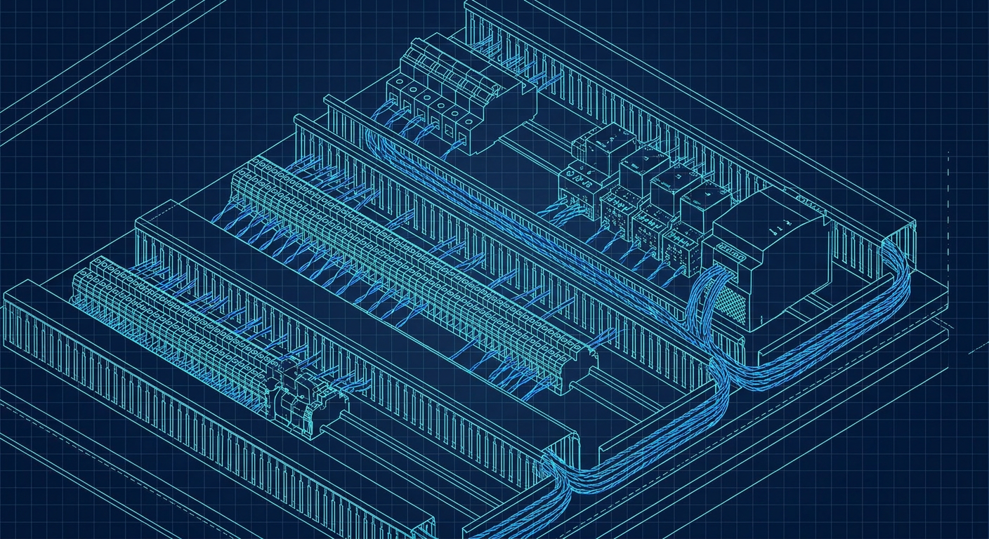
Pop the cover off a wire duct inside a standard automation panel and you will usually see the same problem. You have stiff CAT6 patch cords taking up half the slot width, four separate RS-485 daisy chains held together by screw terminals, and a cluster of protocol gateways translating Modbus RTU into Profinet or EtherNet/IP.
If you build machines or maintain process skids, you know how these panels evolve. You start with an eight-port unmanaged switch, add three Modbus energy meters, hook up a dozen 4-20 mA pressure transmitters, and suddenly your DIN rail is full. You end up buying a larger Hoffman enclosure just to have enough room for wire bend radiuses and 24V distribution blocks.
Single Pair Ethernet (SPE) and its process-industry sibling, Ethernet-APL, are designed to clean out that exact mess. The standards have moved out of working group meetings and trade show booths into shipping transceivers, switches, and field instruments. For anyone who has to lay out a panel, wire a terminal strip, or debug communication drops on a commissioning floor, the physical changes are immediate.
The Physical Layer: Two Wires Replacing Eight
Standard industrial Ethernet (100BASE-TX or 1000BASE-T) requires two or four twisted pairs. Inside an industrial enclosure, those cables are thick, stiff, and annoying to route. A typical industrial CAT6 cable with a PUR jacket has an outer diameter between 6.5 mm and 8 mm. Its minimum bend radius is usually around 40 mm to 60 mm. Try routing six of those into a compact DIN-rail managed switch inside a 400x300 mm box, and you will spend half your assembly time fighting cable tension.
Single Pair Ethernet, defined under various IEEE 802.3 amendments, runs bidirectional data over a single twisted pair of copper wires.
The variant that matters most for control enclosures and field devices is IEEE 802.3cg, specifically 10BASE-T1L and 10BASE-T1S.
10BASE-T1L is the long-reach industrial baseline. It operates at 10 Mbit/s in full duplex over distances up to 1,000 meters (1 km). The cable outer diameter drops to around 3.5 mm to 4.5 mm, which is roughly the size of a standard 18 AWG sensor wire. It uses point-to-point connections, meaning one port on a switch connects to one device or remote node.
10BASE-T1S is the short-reach version. It runs at 10 Mbit/s over distances up to 25 meters, but it adds an optional multidrop mode. In multidrop mode, up to eight or more nodes can share a single unshielded or shielded twisted pair line without needing a switch port for every sensor. It uses physical layer collision avoidance (PLCA) to prevent packets from crashing into each other, giving you deterministic behavior similar to CAN bus, but running pure Ethernet frames.
There are also high-speed SPE variants like 100BASE-T1 (IEEE 802.3bw) and 1000BASE-T1 (IEEE 802.3bp) that run at 100 Mbit/s and 1 Gbit/s over 15 to 40 meters. Those originated in the automotive sector for camera and radar feeds, but for field instruments, energy meters, valve manifolds, and I/O blocks, 10 Mbit/s over 10BASE-T1L is the workhorse.
Ten megabits per second might sound slow if you are used to gigabit office networks. But in the world of 4-20 mA current loops, 9.6 kbit/s Modbus lines, and 31.25 kbit/s Profibus-PA links, 10 Mbit/s is roughly 300 times faster than what is currently running on the plant floor. It is more than enough bandwidth to pull high-resolution process variables, diagnostics, configuration parameters, and web server pages from a field transmitter simultaneously.
Power over Data Line (PoDL)
Running data over two wires helps, but if you still have to pull a separate 24V DC pair to power the device, you are still running four conductors. That is where PoDL (Power over Data Lines, standardized in IEEE 802.3bu and updated in 802.3cg) comes in.
PoDL is the two-wire equivalent of Power over Ethernet (PoE). It couples DC power onto the same twisted pair that carries the high-frequency differential data signal. Inductors at each end block the AC data signal from entering the DC power supply, while capacitors block DC voltage from entering the Ethernet physical layer transceiver (PHY).
The standard defines multiple power classes spanning 12V, 24V, and 48V systems. For industrial automation, the most relevant classes deliver between 10W and 50W to the end device over distances ranging from 100 meters to 1,000 meters.
For a control panel designer, this means you no longer need rows of fused 24V terminal blocks feeding field sensors. You plug the single pair into an SPE switch port equipped with PoDL, and the switch negotiates and supplies the power directly. If a sensor shorts out, the switch port turns off power to that specific channel without bringing down your entire 24V power supply rail or blowing an external glass fuse.
What Ethernet-APL Adds to the Picture
People often mix up Single Pair Ethernet and Ethernet-APL (Advanced Physical Layer). They are related, but they are not identical.
Ethernet-APL is a specific implementation of IEEE 802.3cg 10BASE-T1L developed by a consortium of process industry organizations including FieldComm Group, ODVA, OPC Foundation, and Profibus & Profinet International.
While SPE can be used anywhere (factories, buildings, packaging lines), Ethernet-APL is built specifically for process plants, chemical refineries, wastewater facilities, and oil and gas installations. It takes 10BASE-T1L and adds strict physical layer definitions for intrinsic safety.
Under Ethernet-APL, power and data are certified for use in hazardous areas (Zone 0, Zone 1, Zone 2, and Class I, Division 1 and 2) using the 2-WISE (2-Wire Intrinsically Safe Ethernet) standard (IEC TS 60079-47).
In practical terms, an Ethernet-APL switch or field switch limits the electrical energy (voltage, current, and inductance) on the cable so that even if a technician cuts the wire or shorts the terminals inside an explosive atmosphere, it cannot produce a spark capable of igniting gas or dust.
Before Ethernet-APL, getting Ethernet into a Zone 0 or Class I Div 1 area required heavy explosion-proof junction boxes, rigid metal conduits with poured seals, or isolating barriers that converted digital signals back into slow 4-20 mA analog signals. With APL, you run standard blue intrinsically safe instrument cable directly to the transmitter.
What Actually Drops Out of the Control Enclosure
When you convert a machine panel or a remote I/O cabinet from legacy fieldbuses and analog loops to SPE or Ethernet-APL, the bill of materials changes substantially.
1. Protocol Gateways Disappear
Almost every multi-vendor control panel today contains at least one protocol converter. A typical example is an Anybus or Moxa gateway that translates serial Modbus RTU from a bank of power monitors or variable frequency drives into Profinet or EtherNet/IP for the main PLC.
These gateways are frustrating failure points. They consume DIN rail space, draw 24V power, require custom mapping software, and introduce latency. When a communication fault occurs, the PLC programmer has to figure out whether the problem is on the Ethernet side, the gateway internal register map, or the serial RS-485 bus.
With SPE, devices talk native industrial Ethernet protocols (Profinet, EtherNet/IP, Modbus TCP, OPC UA) directly over the two-wire interface. The gateway is gone. The PLC talks to the device using standard IP sockets and vendor-provided device description files (GSDML or EDS).
2. Analog Input/Output Cards Shrink
In traditional process control, every pressure transmitter, temperature sensor, and flow meter requires a dedicated pair of wires running back to an analog input card on the PLC or distributed I/O rack.
Analog cards are expensive. A high-density 8-channel or 16-channel 4-20 mA HART analog module can easily cost thousands of dollars once you factor in terminal blocks, signal isolators, and surge protectors. You also have to deal with ADC conversion errors, calibration drift, and ground loop noise.
With SPE and Ethernet-APL, field instruments send digital floating-point values directly over the wire. You do not need an analog-to-digital converter card in the cabinet. You replace racks of analog I/O modules with a compact SPE switch.
3. RS-485 Termination and Shielding Headaches End
RS-485 serial networks are cheap, which is why they refuse to die. But they are brittle. If a technician forgets to flip the 120-ohm termination resistor switch at the physical end of the line, or if someone wires a star tap off the main trunk, the entire bus can experience intermittent communication dropouts that take hours to trace with an oscilloscope.
Because 10BASE-T1L uses point-to-point topologies through switches (similar to standard Ethernet), there are no termination resistors to configure, no bus biasing issues, and no daisy-chain reflection problems. If one cable is damaged or disconnected, only that single device drops offline. The rest of the network keeps running.
4. Wire Ducts Shrink by Half
Wire duct fill percentage is a constant headache in panel building. Standards like NFPA 79 and UL 508A set strict limits on how full a wire duct can be (typically 40% to 50% max fill).
Consider an enclosure with 24 field Ethernet connections. Using standard CAT6 industrial patch cables (7 mm diameter), the cable cross-sectional area alone is roughly 923 mm². Factor in the packing density and bend radius, and you need a wide 80x80 mm or 100x80 mm slotted wire duct just to run communication cables along the side of the panel.
Switching to SPE cable (3.5 mm diameter) cuts the cable cross-sectional area to roughly 230 mm², a 75% reduction in copper and jacket volume. You can drop your duct size down to 40x60 mm or free up space for power distribution, allowing you to use a noticeably smaller enclosure footprint.
| Feature | Legacy Setup (RS-485 / 4-20mA / CAT6) | Single Pair Ethernet (10BASE-T1L) | Ethernet-APL (2-WISE) |
|---|---|---|---|
| Conductors | 2 to 8 wires per device | 2 wires (single twisted pair) | 2 wires (single twisted pair) |
| Max Distance | 100m (CAT6) / 1,200m (RS-485) | 1,000 meters | 1,000 meters (Trunk) / 200m (Spur) |
| Bandwidth | 9.6k - 115k (Serial) / 100M (CAT6) | 10 Mbit/s full duplex | 10 Mbit/s full duplex |
| Power Delivery | Separate 24V wires or 4-20mA loop | PoDL (up to 50W) | Intrinsically safe power over bus |
| Cabinet Footprint | Gateways + AI Cards + Wide Ducts | Compact SPE Switch + Narrow Ducts | APL Field Switch + Direct Wiring |
| Addressing | Modbus registers / Dip switches | Standard IPv4 / IPv6 / MAC | Standard IPv4 / IPv6 / MAC |
Terminal Blocks and the Connector Battle
If you look at the physical interface on SPE devices, you will notice that the bulky RJ45 connector is absent. RJ45 was never well suited for harsh factory environments anyway; the plastic latch breaks easily, and sealing it to IP67 requires bulky screw-on housings.
In the SPE world, connectivity is splitting into two clear camps:
Push-in Spring Terminal Blocks: For devices inside control enclosures (IP20 ratings), manufacturers like Phoenix Contact and WAGO are using simple two-pole push-in terminal blocks on DIN-rail modules. You strip the two wires, push them into the spring clamp, and you are done. There are no crimp tools or RJ45 plugs needed.
M8 and M12 Industrial Connectors: For field-mounted devices requiring IP65 or IP67 protection, two primary connector standards have emerged. The IEC 63171-6 standard (backed by Harting, TE Connectivity, and Phoenix Contact) uses a ruggedized industrial pin pattern available in push-pull or M8/M12 screw formats. The competing IEC 63171-1 standard (backed by CommScope) is an LC-style latching connector popular in building automation.
For process plants using Ethernet-APL, standard industrial instrument screw terminals or spring-cage terminals inside standard M20 or 1/2-inch NPT conduit housings remain standard practice. You do not need specialized tooling on site; a standard instrument screwdriver or wire stripper is all your field technicians need.
The Friction Points: What to Watch Out For
SPE is technically mature, but anyone designing systems today needs to know where the practical friction points are.
The first friction point is switch availability. While companies like Phoenix Contact, Harting, Weidmüller, and Endress+Hauser have released SPE and Ethernet-APL switches, the selection is not yet as wide as standard unmanaged RJ45 switches. If you need a switch with an exact mix of six SPE 10BASE-T1L ports and two gigabit fiber uplinks, lead times and catalog options can vary.
The second friction point is field device firmware. When an instrument has a native IP address, it becomes a network endpoint. That means control engineers must think about device firmware updates, IP address allocation schemes (DHCP vs static assignments), and network segmentation down at the individual sensor level.
If you have 150 SPE sensors on a packaging machine, you do not want all 150 devices sitting flat on your main plant control subnet. You need a clean network architecture, usually placing the SPE switches behind managed switches with VLANs or network address translation (NAT) to keep field traffic localized.
From a panel design perspective, layout software is also adapting. When tools like LabCD generate cabinet layouts and terminal block schedules, switching a subnet from multi-conductor analog cables to two-wire SPE drops the terminal block count significantly, but requires tracking PoDL power budget calculations per port so you do not exceed the internal power supply capacity of your industrial switch.
Where to Start Testing
You do not have to redesign your entire product line or plant architecture overnight to get the benefits of two-wire Ethernet.
The easiest place to start is on long field runs that are currently giving you maintenance grief. If you have an RS-485 Modbus RTU run going to an outdoor tank farm, an array of remote flow meters, or a bank of power monitors at the far end of a building, that is your ideal pilot.
Replace the RS-485 serial loop with a 10BASE-T1L point-to-point link. Drop an SPE switch or media converter into the main cabinet and an SPE-enabled I/O block or instrument at the far end.
You will immediately notice the difference: communication diagnostics will show up directly in your PLC engineering environment, packet loss will drop to zero, and you can pull the Modbus translation gateway off your DIN rail for good.
Sources
- https://industrialethernet.net/technology/industrial-ethernet/single-pair-ethernet-and-ethernet-apl-moving-ahead/
- https://www.realpars.com/blog/introduction-single-pair-ethernet
- https://r-stahl.com/en/global/blog/post-detail/13-questions-13-answers-ethernet-apl-is-the-future/
- https://www.phoenixcontact.com/en-pc/technologies/communication-technologies/ethernet-apl
- https://www.automationworld.com/communication/article/55315900/single-pair-ethernet-a-two-wire-cable-is-transforming-industrial-communications
- https://www.microchip.com/en-us/products/interface-networking-connectivity/ethernet/single-pair-ethernet
- https://www.single-pair-ethernet.com/en
- https://www.phoenixcontact.com/en-pc/technologies/single-pair-ethernet