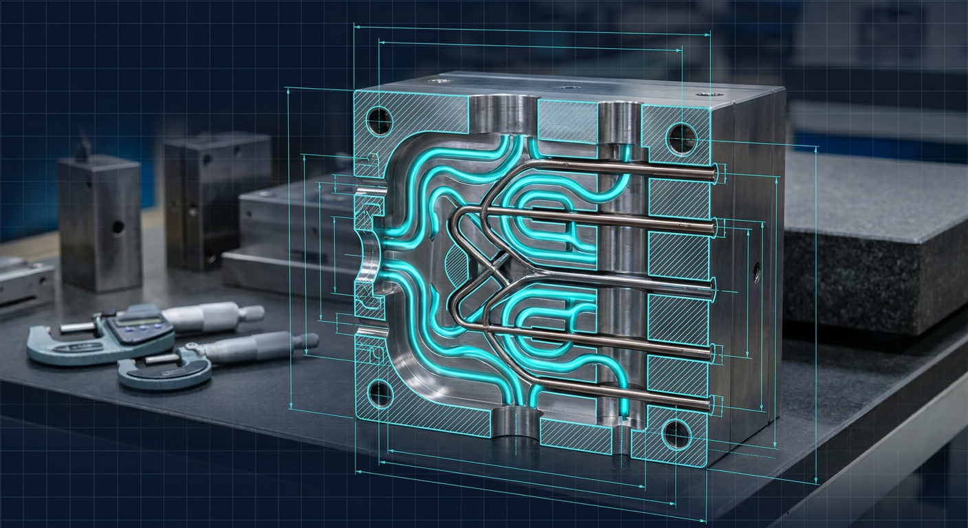
Toolrooms live and die by cycle time, part flatness, and dimensional stability. In injection molding, cooling accounts for roughly 50 to 70 percent of the total cycle time. When a thick boss, a deep rib, or a complex core pull holds heat, the molding technician faces two bad choices. They can lengthen the hold and cooling stages, which burns margin on every shot. Or they can eject early, which warps the part, pulls draft angles out of square, and risks having moving slides bind on hot plastic.
Over the past year, generative thermal software like Diabatix, nTopology, and design tools referenced by Leo AI have pushed conformal cooling into production tool design. Instead of relying on intersecting straight gun-drilled holes, baffles, and bubbler tubes, these algorithms generate organic internal cooling channels that sweep equidistant along complex cavity and core geometry. Data from additive tooling trials at companies like Meltio and voestalpine consistently report cycle-time reductions between 20 and 40 percent alongside tighter part tolerances.
Yet on the shop floor, replacing standard P20 steel blocks with direct metal laser sintered (DMLS) inserts introduces mechanical and kinematic headaches that software vendors rarely discuss. When an organic fluid volume meets slide mechanisms, ejector pins, tight parting line shut-offs, and post-weld heat treatment, the design problem shifts from pure heat transfer to toolroom mechanics. Tool designers and manufacturing engineers need to understand the true trade-offs before approving a five-figure additive tooling build.
The Mechanical Bottleneck in Conventional Mold Cooling
Traditional mold manufacturing relies on subtractive operations. Water channels are gun-drilled through P20 (1.2311), H13 (1.2344), or 7075 aluminum tool plates. Gun drilling is predictable, rigid, and inexpensive, but it is strictly linear. A drill bit moves in a straight vector.
When cooling a contoured part, such as an automotive connector housing, a deep-draw robotics enclosure, or an impeller, straight drilled lines cannot track the cavity surface. The water line might sit 8 mm away from the root of a rib but 35 mm away from the tip of an adjacent core. This variance creates sharp thermal gradients across the mold face.
These thermal gradients cause distinct mechanical failures:
- Differential shrinkage and warpage: Slower cooling regions continue to shrink long after the skin freezes, pulling thin walls out of plane and twisting datum surfaces.
- Ejection pin push-through: Hot spots leave plastic soft near ejector pins. When the hydraulic or mechanical ejector plate fires, pins push into soft resin instead of clearing the part from the core.
- Dynamic slide binding: Differential thermal expansion between a hot mold core insert and a cooler guide block causes mechanical slides and angle pins to gall or seize during high-speed cycling.
- Sink marks on cosmetic faces: Uneven thermal mass pulls plastic away from cavity walls opposite thick internal mounting bosses.
To manage these hot spots, toolmakers have historically inserted copper-beryllium (CuBe) or high-conductivity Ampcoloy plugs, or installed mechanical baffles that split a drilled bore into forward and return paths. Baffles help, but they add leak paths, create stagnant flow dead zones, and clog with scale over thousands of cycles.
How Generative AI Solves Thermal Gradients
Generative thermal algorithms take a different approach. Rather than requiring a tooling engineer to manually sketch spline paths and loft variable pipes, solvers use topology optimization and computational fluid dynamics (CFD) to grow fluid volumes directly inside the core CAD space.
The algorithm operates against clear boundary conditions: the molten plastic heat flux profile, the required mold surface temperature target, the coolant inlet temperature, allowable pressure drop across the circuit, and exclusion zones for mechanical hardware.
The resulting geometry is rarely a simple pipe. Generative solvers produce branching networks reminiscent of vascular structures or flattened ribbon channels. By modulating channel cross-sections, the solver accelerates coolant velocity near high-heat zones to maintain turbulent flow (typically aiming for a Reynolds number above 4,000 to maximize the heat transfer coefficient) while widening passages elsewhere to keep overall pressure drop within standard mold temperature control unit (TCU) pumping limits.
By keeping water channels at a continuous, uniform offset from the molding face (often 3 to 5 mm depending on steel strength and injection pressure), the insert extracts heat uniformly. Molten resin freezes evenly across thick and thin sections alike. Core temperatures drop rapidly, allowing the press to open seconds earlier without part deformation.
The Hidden Toolroom Costs of Additive Tooling Inserts
Conformal cooling sounds like an obvious choice until the toolroom gets the bill for the printed metal insert and confronts the downstream post-processing.
Most conformal inserts are printed via Laser Powder Bed Fusion (LPBF / DMLS) using 1.2709 Maraging steel (also known as 18Ni300) or specialized stainless tool steels like Uddeholm Corrax. While the printing process produces dense metal (typically greater than 99.8 percent relative density), the mechanical and metallographic realities demand careful planning.
Material Conductivity Differences
Standard P20 pre-hardened tool steel has a thermal conductivity around 29 to 32 W/m-K at standard operating temperatures. Maraging 1.2709 tool steel has a lower base thermal conductivity, roughly 15 to 20 W/m-K in its printed and aged state. If a generative conformal channel is poorly positioned, a printed maraging steel core can actually run hotter than a conventionally drilled P20 or beryllium-copper insert. The geometric advantage of conformal routing must outweigh the lower intrinsic bulk conductivity of the additive alloy.
Thermal Stress and Post-Heat-Treatment Warpage
LPBF processes build parts layer by layer, introducing severe residual tensile stresses. Before removing the insert from the build plate, it must undergo a stress-relief heat treatment, followed by an aging treatment to harden the maraging steel from roughly 32 HRC as-printed up to 50 to 54 HRC. During these thermal cycles, the block moves. Critical datum faces, dowel locating bores, guide pin holes, and parting line shut-offs will distort.
A tool designer cannot simply print a net-shape insert and drop it into an A-plate pocket. Every mechanical interface must be printed with 0.5 to 1.5 mm of green machining stock, then finish-milled, wire-EDM cut, or ground back to target dimensions after heat treatment.
Internal Channel Surface Roughness and Powder Evacuation
As-printed internal channels in DMLS parts have a high surface roughness ($Ra$ between 8 and 15 micrometers). While this roughness can stimulate turbulent coolant flow, it also creates high pressure drops and acts as a collection site for mineral scaling and particulate buildup from industrial cooling towers. Furthermore, clearing unmelted metal powder from serpentine, branching generative channels requires ultrasonic baths, pressurized flushing, and borescope inspection before the insert enters service. Trapped powder left behind can break loose during production, instantly clogging water manifolds and seizing proportional valves.
Tooling Comparison: P20 Gun-Drilled vs Generative Conformal Insert
The following illustrative composite comparison brings together cycle, tooling, and post-processing figures typical for a high-volume automotive electrical housing mold running 30 percent glass-filled PA66 (polyamide) across a 1,000,000-shot production run.
| Metric / Parameter | Conventional Gun-Drilled P20 Tooling | DMLS 1.2709 Generative Conformal Insert | Notes and Mechanical Context |
|---|---|---|---|
| Insert Fabrication Method | 3-axis CNC milling + Gun drilling | LPBF 3D Print + Post-CNC / Wire EDM | Insert dimensions: 120 x 85 x 90 mm |
| Core Insert Hardness | 30-34 HRC (Pre-hard P20) | 50-52 HRC (Maraging aged) | Printed insert has higher abrasion resistance |
| Cooling Channel Geometry | 3x 8mm straight gun-drilled bores + 2 baffles | Generative bifurcated channels (4-7mm var.) | Algorithmic path tracking complex top ribs |
| Initial Insert Manufacturing Cost | $2,200 | $6,800 | Includes print time, powder, and post-machining |
| Post-Processing Machining Time | 6 hours total mill/drill | 14 hours (Stress relief + Wire EDM + 5-axis finish) | Datum bores and shut-offs ground post-aging |
| Mold Cavity Surface Temp Delta | 18 degrees C variance across core face | 4 degrees C variance across core face | Measured at mold open cycle state |
| Cooling Phase Duration | 14.5 seconds | 8.8 seconds | 39.3% reduction in cooling stage |
| Total Press Cycle Time | 24.2 seconds | 18.1 seconds | 25.2% reduction in overall machine time |
| Part Warpage (Datum Runout) | 0.38 mm total indicator reading | 0.09 mm total indicator reading | Flatness across critical sealing face |
| Slide Clearance Stability | Requires 0.035 mm slide clearance | Runs reliable at 0.018 mm slide clearance | Lower thermal expansion prevents slide galling |
Looking at the numbers, the generative insert costs more than three times the conventional P20 core up front ($6,800 versus $2,200). However, on an automated press with a shop rate of $95 per hour, dropping the cycle time by 6.1 seconds saves roughly 1.7 hours of machine time per 1,000 parts. On a 500,000-shot run, that cycle reduction recovers over $80,000 in machine capacity while slashing scrap rates from out-of-spec warpage.
For low-volume production (under 50,000 shots), the CapEx and EDM setup time of additive inserts rarely pay back unless the part geometry cannot meet flatness tolerances by any other means.
The Dead Mesh Problem in Mold Assembly Kinematics
A critical failure mode in generative mold engineering is the CAD data format. Many generative thermal engines export geometry as high-density polygon meshes (STL, OBJ) or boundary meshes converted to uneditable, frozen STEP solids with thousands of tiny NURBS patches.
An injection mold is not a static sculpture. It is a high-speed kinematic machine. A typical injection tool contains hundreds of mating components: leader pins, bronze bushings, slide retainers, gibs, angle pins, lifters, core pulls, ejector sleeves, limit switches, and O-ring sealing grooves.
When a generative design tool exports a dead mesh for the cooling channel or the entire insert block, tool designers encounter severe CAD integration barriers:
- Parametric Feature Loss: You cannot easily tap a standard 1/4-inch NPT or BSPP coolant port onto a faceted mesh face without rebuilding the geometry.
- Interference Detection: CAM and mold simulation systems struggle to perform precise interference checks between dynamic ejector pins and faceted channel boundaries, leading to costly EDM crashes or drilled water leaks during assembly.
- O-Ring Sealing Failures: Coolant transfer between the machine base plate and the insert relies on compressed Viton O-rings in counterbored gland pockets. If the insert geometry cannot support precise parametric face tolerances (flatness within 0.005 mm and fine surface finishes), coolant under 4 to 6 bar pressure will leak into the ejector housing.
- Draft Angle Modifications: If mold flow trials show that a deep rib requires an additional 0.5 degrees of draft to prevent dragging, a dead mesh cannot be tweaked parametrically. The engineer must rerun the entire generative solver and re-export the entire solid.
To bridge this gap, modern tool design demands hybrid modeling. The generative thermal core must live as an editable parametric B-rep body inside the parent CAD environment, allowing the water paths to update alongside parting line shifts, ejector pin relocations, and mechanical slide clearances.
          +-------------------------------------------------------------+
          |            Parametric Part & Cavity Solid Model             |
          +-------------------------------------------------------------+
                                         |
                   +---------------------+---------------------+
                   |                                           |
                   v                                           v
    +-----------------------------+             +-----------------------------+
    | Conventional Gun-Drilled    |             | Generative Conformal Core   |
    | P20 Steel Core Insert       |             | DMLS 1.2709 Tool Steel      |
    +-----------------------------+             +-----------------------------+
    | - Low initial tool cost     |             | - 20-40% cycle time drop    |
    | - Standard CNC / drill shop |             | - Tight thermal uniformity  |
    | - High thermal variance     |             | - High additive / EDM cost  |
    | - Warpage & slide binding   |             | - Risk of dead-mesh lock    |
    +-----------------------------+             +-----------------------------+
                   |                                           |
                   +---------------------+---------------------+
                                         |
                                         v
          +-------------------------------------------------------------+
          | Tooling Assembly Kinematics (Slides, Lifters, Ejector Pins) |
          +-------------------------------------------------------------+
Practical Decision Frame: When to Specify Generative Conformal Cooling
Tooling engineers and manufacturing leads should apply a structured checklist before specifying DMLS conformal inserts over conventional machining:
1. Evaluate Part Geometry and Wall Distribution
- Use Conformal Inserts: When the plastic component has non-uniform wall sections, deep standing cores (length-to-diameter ratio greater than 3:1), or aggressive contours where straight drilled lines leave more than 15 mm of uncooled steel.
- Use Conventional Machining: When the part is broadly planar with uniform nominal wall thickness (under 2.5 mm) where gun drilling combined with standard baffles maintains a surface offset variation below 6 mm.
2. Verify Mechanical Hard Points and Clearances
- Maintain at least 3 mm of solid steel between any conformal water channel and an ejector pin bore, leader pin pocket, or parting line shut-off face.
- Ensure water channel geometry allows a minimum 1.5-diameter straight entry and exit for tapping standard tapered or parallel pipe threads (NPT/BSPP) or press-fit quick-connect couplings.
- Model dynamic slide envelopes under full thermal expansion. Ensure slide wear plates and gibs sit isolated from rapid thermal swings to maintain 0.015 to 0.025 mm running clearances.
3. Check Water Quality and Pressure Constraints
- Generative channels with complex cross-sections require clean, filtered, and chemically treated closed-loop chiller circuits. If the molding shop runs open-tower untreated water, narrow conformal channels will scale up within months, degrading thermal performance.
- Keep total circuit pressure drop below 2.5 bar at design flow rate to ensure the shop's existing TCU pumps can deliver turbulent flow without cavitation.
4. Calculate Economic Break-Even
- Multiply the projected cycle time reduction (seconds saved per shot) by the total production run volume to establish total press hours saved.
- Compare press hour cost savings against the incremental delta of DMLS printing, stress-relieving, and post-machining EDM finishing over a CNC-milled P20 block.
- Factor in quality costs: if part warpage drops from 0.4 mm to 0.1 mm, calculate the scrap reduction and automated assembly yield improvements.
What This Means for Mexaio AI
Generative design cannot stop at producing an isolated organic heat exchanger. For tooling engineers, a mold is a kinematic machine where fluid mechanics, thermal expansion, slide clearances, and ejector mechanisms intersect under hundreds of tons of clamping pressure.
Tools like Mexaio AI approach this problem by integrating parametric kinematics, mechanism synthesis, and manufacturing constraints directly into the generative process. Instead of spitting out disconnected polygonal geometry, modern generative engineering must produce fully editable, B-rep solid models that respect draft angles, slide strokes, bolt circles, and machine clearances. When internal fluid passages adjust automatically without breaking mating constraints or kinematic actions, mold designers can optimize thermal performance while maintaining toolroom manufacturability.
How to Move Forward on the Shop Floor
If you are planning your next high-volume tooling build, do not jump straight into a full-mold additive build. Start by isolating the single hottest core or dynamic slide insert in your tool that currently limits the cooling timer.
Work with your design team to generate a parametric conformal insert, ensure minimum wall clearances to ejector pins are strictly locked in B-rep CAD, and quote the insert with both additive printing and post-heat-treatment wire EDM finishing included. Measure the actual cycle time reduction, cavity temperature delta, and parting line dimensional stability directly on the press. Conformal cooling is no longer experimental, but its success depends on respecting the mechanical and kinematic realities of the toolroom.