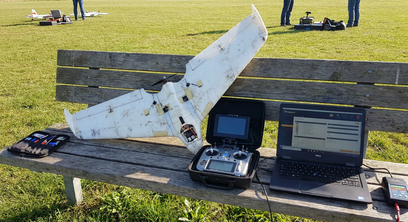
Every long-range flyer has felt that sudden spike of adrenaline when the video feed flickers, the on-screen display flashes zero satellites, and your favourite foam wing vanishes behind a line of trees. Discussions on the IntoFPV and ArduPilot community forums over the past couple of weeks show that GPS glitches remain the single biggest reason why autonomous return-to-home setups fail in the field. Pilots buy a twenty-dollar M8N or M10 GPS puck, solder four wires to an F405 flight controller, flip the RTH switch on their radio, and assume the plane will always fly straight back to the pits.
Then a real-world glitch happens. Radio frequency noise from an onboard HD camera jams the L1 frequency band, a loose connector drops the serial telemetry line, or a fast bank angle shades the ceramic antenna from the sky. If your flight controller is not configured to handle lost satellites gracefully, standard return-to-home logic can command full down elevator, cut the motor entirely, or send the airframe into an endless spiral into the brush.
Setting up a bulletproof return-to-home routine on INAV and ArduPilot is not difficult, but it requires understanding what the software does when its primary navigation sensor goes dark. Here is how to configure compass fallbacks, emergency climb throttles, and dead-reckoning modes so your model actually makes it back to the flying patch.
The Common Ways GPS Fails in the Air
GPS pucks do not fail because the satellite constellation stops working. They fail because small RC airframes are hostile electrical environments. The most frequent culprit on a modern FPV build is broadband RF noise generated by switch-mode voltage regulators, unshielded digital video transmitters, and HD recording cameras like the RunCam Thumb or DJI O3 unit. When placed within ten centimeters of a ceramic GPS patch, this electronic noise floor easily overpowers the tiny signals arriving from orbit.
Another major cause is antenna shadowing. Fixed-wing aircraft bank during turns. If your GPS module sits flat on the fuselage deck right next to a tall 5.8GHz video antenna or a chunky 4S lithium-ion pack, tilting forty degrees into a hard turn can block line-of-sight to half the satellite constellation. When the visible satellite count drops below six, the horizontal dilution of precision (HDOP) spikes. The flight controller suddenly believes the plane has jumped three hundred meters sideways in a fraction of a second.
In both INAV and ArduPilot, an abrupt position jump triggers a GPS glitch flag. If the firmware is left on default settings, the autopilot tries to correct this phantom drift by rolling hard in the opposite direction. On an aggressive flying wing, that sudden violent command can induce an unrecoverable stall or a high-speed dive.
INAV Emergency Failsafe and Sensor Loss Behavior
INAV has become the go-to firmware for fixed-wing pilots who want a straightforward setup without digging through thousands of parameters. But its default safety profile requires careful adjustment for fixed-wing flight.
In standard INAV firmware, Return-to-Home relies on two core sensors: the GPS for position and ground track, and the barometer for altitude holding. When you flip your programmed RTH switch, the aircraft climbs to your configured safe altitude, points its nose toward the coordinates recorded during arming, and throttles up to cruise speed. However, if the GPS lock drops while RTH is already active, INAV enters an emergency fallback state. By default, older configurations could drop into an emergency descent mode that simply lowers the nose and idles the throttle to bring the craft down wherever it happens to be.
To prevent your wing from descending into a swamp or thick forest miles from the field, you need to configure your failsafe stages properly in the INAV Configurator:
- Set Stage 1 Failsafe to hold position or stabilize for one full second. This smooths over momentary control link glitches caused by brief antenna nulls without triggering an immediate panic climb.
- In Stage 2 Failsafe, select RTH rather than Land or Drop. Ensure that the 'RTH Altitude' is set high enough to clear the tallest trees, mobile towers, or power lines between your flight path and the flight line. Fifty to seventy meters above ground level is standard for most open fields.
- Configure 'Emergency Landing' behavior. If GPS position data drops entirely, you do not want an immediate motor cut. Set the emergency landing throttle to your stable level-cruise value so the plane maintains flying airspeed in a shallow glide rather than stalling instantly.
- Enable Nav Dead Reckoning where supported. On modern INAV releases, the firmware uses inertial sensor data to hold the last known compass heading and pitch attitude for several seconds if satellite updates pause, giving the GPS time to reacquire its fix without the plane wobbling out of control.
Critical INAV CLI Settings for Wings
To ensure your wing behaves smoothly during unexpected dropouts, open the CLI tab in INAV Configurator and verify the following baseline variables:
set nav_rth_climb_first = ON
set nav_rth_climb_ignore_emerg = OFF
set nav_fw_cruise_thr = 1450
set nav_fw_pitch2thr = 10
set nav_fw_min_vel_ms = 7
set failsafe_recovery_delay = 5
save
Enabling nav_rth_climb_first guarantees that the airframe applies power and gains altitude before attempting to turn around. If you lose video or control link low behind a tree line, turning immediately without climbing can drag a wingtip through branches. Setting nav_fw_pitch2thr ensures that whenever the nose pitches up to gain altitude, the flight controller automatically adds throttle to prevent an airspeed stall.
ArduPilot Dead Reckoning and EKF Navigation
ArduPilot handles sensor degradation through its Extended Kalman Filter (EKF3). Unlike simpler flight controllers that switch abruptly between distinct sensor modes, the EKF constantly fuses accelerometer, gyroscope, barometer, compass, and GPS readings into an integrated mathematical state estimate. It continuously tracks the health of each sensor.
When ArduPilot detects that GPS data is drifting or failing, it raises a GPS Glitch message and temporarily disregards satellite position updates. Instead of diving or disarming, the system falls back onto dead reckoning. In dead-reckoning mode, ArduPilot uses estimated airspeed, wind estimation, and the onboard compass heading to calculate where the plane is and steer back toward home.
+-------------------------------------------------------------------------+
|                 ArduPilot Sensor Loss Transition Path                   |
+-------------------------------------------------------------------------+
|  Healthy Flight: Fusion of GPS (position) + Baro (alt) + IMU (attitude) |
|                                    |                                    |
|                      [ GPS Signal Disrupted ]                           |
|                                    v                                    |
|  EKF Glitch Detection: GPS weight set to 0; compass & airspeed fused    |
|                                    |                                    |
|                      [ Dead Reckoning Active ]                          |
|                                    v                                    |
|  Fallback Navigation: Steers Home via Compass Heading & Cruise Throttle |
|                                    |                                    |
|                      [ GPS Signal Restored ]                            |
|                                    v                                    |
|  Smooth Re-convergence: EKF restores full satellite position tracking   |
+-------------------------------------------------------------------------+
For fixed-wing planes running ArduPlane, setting up dead reckoning is remarkably effective, even on airframes without an external pitot tube. ArduPilot contains synthetic airspeed estimation algorithms that calculate forward speed based on throttle output, pitch angle, and accelerometer drag measurements.
Essential ArduPlane Parameters for Reliable Recovery
To make sure ArduPlane survives satellite lock loss, adjust these core parameters in Mission Planner:
FS_LONG_ACTN: Set this to1(Return to Launch). When the RC receiver link drops for more than a few seconds, the autopilot initiates an RTL sequence.RTL_AUTOLAND: Set to0unless you have thoroughly tuned and tested an autonomous reverse-thrust landing approach at your home field. You want the plane to loiter safely overhead while you regain video or manual line-of-sight.RTL_ALTITUDE: Set to at least 5000 (representing 50 meters in centimeters) to stay well clear of local ground clutter.EK3_SRC1_POSXY: Set to3(GPS). Ensure your secondary fallback sources are properly mapped.AHRS_WIND_MAX: Set this to match local flying conditions (typically 10 to 15 m/s). This allows the synthetic wind estimator to maintain realistic ground track corrections when flying on compass heading alone.
The Compass Question: External Magnetometer vs Compassless Drift
One of the fiercest debates at the club field is whether a fixed-wing FPV model should use a compass. Multirotors absolutely require a compass to know which way they are facing before they start moving. Fixed-wing aircraft, however, are constantly in forward motion, meaning the flight controller can calculate course heading directly from GPS track over ground.
On compact foam wings, motor power leads running through the fuselage generate massive magnetic fields whenever you advance the throttle. If you mount a cheap GPS module with an internal magnetometer directly above the main 60A battery lead, the compass reading can swing forty degrees the instant you punch the throttle to climb. In INAV, a magnetically confused compass is worse than having no compass at all; it can cause the plane to circle endlessly in a toilet-bowl pattern.
| Configuration Profile | Primary Advantages | Common Pitfalls | Recommended Airframe Types | Typical Cost (USD) | Source Notes | | :--- | :--- | :--- | :--- | :--- | :--- | :--- | | GPS-Only (No Compass) | Immune to motor current interference; zero calibration needed | Heading unknown while stationary; requires forward airspeed to track | Swept wings, fast twin-tractors, park flyers | $14 - $22 (e.g. Beitian BN-220 / M100) | Standard club consensus & intoFPV guidelines [2][12] | | GPS with Mast-Mounted Compass | Instant heading at zero speed; supports true stationary dead reckoning | Susceptible to magnetic interference if mounted too close to batteries | Long-range cargo wings, twin-boom pushers, mapping airframes | $25 - $45 (e.g. Matek M10-CAN / Holybro Micro) | ArduPilot Fixed-Wing documentation [13][16] | | Dual GPS Array (ArduPilot) | Instant yaw calculation without magnetic compass; fault-tolerant | Higher power consumption; requires two UART ports and airframe real estate | Giant-scale gas models, large composites (1.8m+ wingspan) | $60 - $110 (Dual M10 setup) | Dronelife & ArduPilot community builds [1][13] |
Note: The performance characteristics and prices in this table represent typical hobby-grade components and established firmware behavior compiled from ArduPilot and INAV community deployment data. [2][12][13]
For ninety percent of hobby FPV wings under 1.2 meters, disabling the magnetometer entirely in software and relying on GPS heading is the most reliable choice. If you choose to fly without a compass, you must configure your flight controller to rely strictly on dynamic GPS heading once the plane accelerates above 3 m/s.
Physical Installation: Protecting Your GPS from Onboard Noise
Software settings cannot save a plane if the hardware installation is fundamentally flawed. A few clean build habits will double your visible satellite count and cut lock-acquisition times at the field:
- Maintain Physical Separation: Mount your GPS module at least fifteen centimeters away from video transmitters, flight cameras, and main battery power wires. On a flying wing, the outer wing panel or the dorsal vertical fin is the ideal spot.
- Shield the Underside: Place a small square of adhesive copper tape beneath the GPS puck, insulated with Kapton tape. This acts as a ground plane, blocking electromagnetic hash emitted by servos and ESC switching regulators buried inside the foam fuselage.
- Ferrite Chokes on Long Leads: If you run a long four-wire silicone harness from an outer wing bay back to the fuselage flight controller, slip a tiny ferrite ring over the cable near the flight controller. This stops the harness from acting as an antenna that carries radio frequency noise directly into the receiver circuitry.
- Wait for a Solid Cold Lock: Never rush your pre-flight routine. When you plug in your pack at the field, let the airframe sit stationary on the flight table for two to three minutes. Do not arm or launch until your on-screen display shows at least eight satellites and the home point distance displays zero meters.
Field Verification: The Three-Step Failsafe Checklist
Before trusting your plane on a long cruising flight, perform this three-step test protocol at the field:
- Bench Test with Props Off: Connect the aircraft on your bench without propellers. Arm the model, throttle up slightly to engage navigation modes, and toggle your programmed RTH switch on your transmitter. Verify in the OSD that the flight mode changes to RTH and that the control surfaces deflect smoothly to initiate an upward climb.
- Line-of-Sight Switch Test: Take off in manual or angle mode, climb to fifty meters directly in front of you, and flip the manual RTH switch while keeping your eyes on the plane. The motor should increase power to your configured cruise throttle, the nose should rise to establish a steady climb, and the plane should turn smoothly toward the launch point before beginning a circle overhead.
- Simulated Link Failsafe: At safe altitude and within visual line of sight, switch off your radio transmitter. The plane's receiver should trigger Stage 2 failsafe within one second, engaging RTH automatically. Verify the plane heads home, then power your transmitter back on, switch out of RTH mode, and regain manual control to land.
What this means for MyRC
Building dependable autonomous airplanes should not require spending weeks parsing obscure forum threads or guessing CLI settings. At MyRC (myrc.ai), we believe that practical RC flying is rooted in clean hardware layouts, dependable open-source firmware presets, and field-tested safety procedures. By simplifying the way modelers plan electronics layouts, verify weight-and-balance, and configure sensor fail-safes, hobbyists spend less time hunting through brush for lost airframes and more time enjoying smooth flights at the field.
Direct Answer: How to Prevent Flyaways from GPS Dropouts
To keep an RC plane from flying away when satellite lock drops, disable the physical magnetometer on small foam airframes to eliminate motor interference, configure your flight controller failsafe to climb before turning, and set an emergency cruise throttle that maintains stable airspeed rather than idling the motor. If the GPS drops signal, the aircraft will hold a level compass heading and safe altitude until satellites reacquire instead of entering an immediate stall or dive.
Sources
- IntoFPV: ArduCopter to iNav Setup and Compass Guidelines
- INAV Flight Firmware Official Documentation: Failsafe and Recovery Modes
- INAV Fixed Wing Group: Return to Home and Mode Configuration Guide
- ArduPilot Discourse: GPS Glitches and EKF Estimation in Flight
- Emlid Community: GPS Glitch Behavior and Failsafe Control in Fixed-Wing Aircraft
- Austin RC Flight Group: Preventing Lost Aircraft Incidents with GPS Return to Home