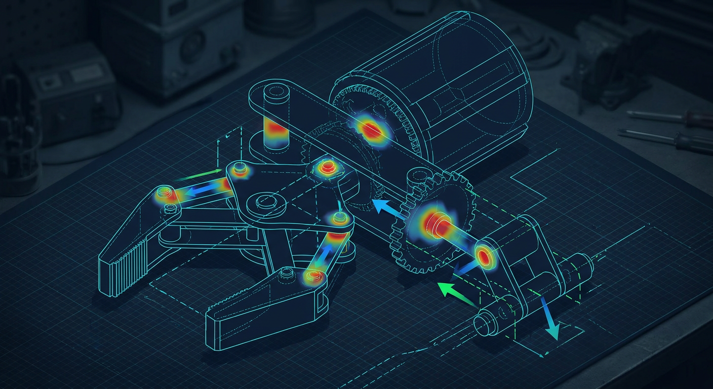
MIT CSAIL recently detailed new pipelines, including systems like PhysicsGen and synthetic environment generators, designed to build automated virtual playgrounds for training robotic manipulation policies. The premise is compelling. Instead of spending months hand-crafting digital twins or manually logging teleoperation runs, generative AI agents configure thousands of randomized physical environments where neural network policies learn to grasp, orient, and assemble parts. Coupled with emerging world models like Genesis and simulation platforms built on Drake and PhysX, the timeline from concept to reinforcement learning policy has shrunk from weeks to hours.
Yet on the shop floor, machine shops and mechanism builders are noticing an expensive disconnect. A control policy trained inside an auto-generated physics simulation commands a four-bar linkage gripper to close on an asymmetrical workpiece. In simulation, the gripper adapts smoothly, the penalty function converges, and the gripper reports a secure hold. When that same policy executes on physical aluminium and steel hardware, the gripper binds at mid-stroke, the servo draws 4.8 amps against a hard mechanical stall, and the motor driver blows its thermal cut-off within forty seconds.
This failure is not a flaw in the control architecture. It is a failure of mechanism kinematics inside the simulation asset itself. When synthetic training pipelines treat a mechanical end-effector as a loose collection of rigid bodies tied together by frictionless ideal revolute joints, the simulation invents compliance that does not exist in solid metal. If you build custom grippers, robotic tooling, or five-bar planar mechanisms, feeding inaccurate kinematics into an RL simulator does not just generate poor policies. It ruins hardware.
The Lie of the Ideal Joint in Synthetic Environments
Most generative physics environments rely on game-engine-derived physics cores or simplified rigid-body impulse solvers. To keep simulation speeds at ten thousand frames per second across parallel GPU instances, these solvers make deliberate mathematical compromises. Joints are treated as perfectly rigid mathematical constraints with zero clearance, zero runout, zero thermal expansion, and a single Coulomb friction coefficient applied uniformly across all degrees of freedom.
Real mechanisms built in a precision machine shop behave nothing like this. Consider a standard parallel gripper actuated by a symmetrical four-bar linkage using 303 stainless steel dowel pins pressed into 7075-T6 aluminium links.
In the physical part, each joint brings a specific tolerance class. An H7/h6 sliding fit gives between 0.004 mm and 0.012 mm of radial play on an 8 mm pin. When the mechanism is open and unloaded, this clearance allows the links to articulate with minimal friction torque, typically under 0.03 Nm. But apply an off-axis grasping force of 45 N at the fingertip, and the kinematic behavior changes instantly:
- The off-axis moment twists the driving link around its longitudinal axis.
- The 0.008 mm bore clearance allows the pin to cock slightly within the bushing, shifting contact from a distributed line load to two high-pressure edge contacts.
- The local contact stress spikes past 120 MPa, breaking down the boundary lubrication film.
- The effective joint friction coefficient jumps from 0.08 (lubricated steel on bronze) to 0.35 (galled boundary contact).
If the generative physics engine assumes a static joint friction coefficient of 0.05, the RL agent learns to exploit contact angles that rely on high lateral loading during insertion tasks. On real hardware, that lateral load cocks the pins, drives joint friction above the maximum torque output of the actuator, and stalls the mechanism.
+-------------------------------------------------------------------------+
|                 THE MECHANISM SIM-TO-REAL FAILURE LOOP                  |
+-------------------------------------------------------------------------+
|                                                                         |
|  [ Synthetic AI Sim ]  --> Assumes ideal joints & frictionless planes   |
|          |                                                              |
|          v                                                              |
|  [ Policy Optimization ] -> Exploits unmodeled joint compliance         |
|          |                                                              |
|          v                                                              |
|  [ Physical Deployment ] -> Off-axis load cocks dowel pins in H7 bores  |
|          |                                                              |
|          v                                                              |
|  [ Hardware Consequence] -> 120 MPa edge contact, friction spike,       |
|                             servo thermal trip, stripped gearbox        |
+-------------------------------------------------------------------------+
Multi-Link Over-Constraint and Kinematic Singularity
Generative simulation tools frequently misrepresent closed kinematic chains. Open-chain serial manipulators like a six-axis arm are mathematically straightforward: each joint position maps directly to an end-effector pose through forward kinematics. Closed-chain mechanisms, such as five-bar linkages, parallel delta stages, or toggle-clamp grippers, require loop-closure constraints that must be satisfied simultaneously at every time step.
When synthetic environment pipelines spawn randomized mechanisms or parametric variations of a gripper, they often build closed chains by adding joint constraints between independently spawned bodies. If the kinematic loop equations are not explicitly solved and checked for mobility, the physics engine uses soft spring-damper penalties to enforce closure.
This introduces artificial compliance. The simulation allows closed linkages to stretch by 0.5 mm at the joints to clear kinematic singularities. A policy trained in this environment will happily drive the mechanism straight through a singularity position, such as a toggle-lock dead point where the links align at 180 degrees, because the solver stretches the simulated joints to bypass the mathematical infinity in joint torque.
When that policy commands the physical gripper to pass through the same toggle point, the mechanical links cannot stretch. The 7075 aluminium arms experience pure axial compression. The mechanical advantage at the toggle point approaches infinity, and the drive motor cannot generate the displacement required to break the lock. The result is a mechanical jam that requires a technician to manually loosen the drive yoke with an Allen key.
Illustrative Friction and Jamming Thresholds
To show how contact physics diverge between simulation assumptions and shop-floor reality, consider an illustrative composite based on typical bench measurements of an 8 mm dowel joint in a 6061-T6 linkage under varying side loads.
| Operational Parameter | Default Synthetic Sim | Real Measured Mechanism (Bench Composite) | Practical Impact on Policy Transfer |
|---|---|---|---|
| Radial Bore Clearance | 0.000 mm (Rigid Constraint) | 0.009 mm (H7/h6 Reamed Fit) | Link cocking under asymmetrical load |
| Static Pin Friction (Unloaded) | 0.05 (Constant) | 0.07 to 0.09 (PTFE Grease) | Negligible error at low velocities |
| Friction Under 30 N Side Load | 0.05 (Constant) | 0.28 to 0.34 (Edge Contact) | Actuator stalls at 65% rated travel |
| Joint Radial Compliance | 0.250 mm (Soft Penalty) | 0.002 mm (Elastic Modulus) | Artificial pass-through at singularities |
| Backlash Hysteresis | 0.00 degrees | 0.42 degrees total loop | Inability to maintain precise tool force |
Notice the stark contrast in side-load friction. In synthetic simulators, increasing the normal load increases the drag linearly according to elementary friction models. In real metal joints, side loading induces moment tipping inside the bore, creating two-point contact that escalates effective resistive torque by more than 300 percent.
The Danger of Training Policies on Unmachinable Geometry
Synthetic environment generators often produce visual geometries that look functional but ignore the physical realities of subtractive and additive fabrication. When an AI agent generates a mechanism assembly, it may position bearing pockets with zero tool clearance, specify internal sharp corners that a 3 mm end mill cannot cut, or place fasteners in locations where an assembly driver cannot fit.
If the engineering team attempts to modify the CAD model after policy training to make it manufacturable, such as changing an internal pocket corner radius from 0 mm to 2.5 mm, adding 1.5 mm of wall thickness to prevent deflection, or swapping a custom bronze sleeve for an off-the-shelf sintered bushing, the kinematic and dynamic properties change:
- The link mass increases by 18 percent, shifting the center of gravity outward.
- The mass moment of inertia around the pivot axis increases with the square of the distance.
- The natural frequency of the gripper structure drops, causing resonance at the policy loop update rate (often 50 Hz to 100 Hz).
Because the reinforcement learning policy was tuned to the razor-thin margins of the unmachinable model, this post-hoc engineering rework breaks the policy. The robot exhibits high-frequency limit-cycle oscillations, overshoots grasping targets, or drops parts due to sluggish acceleration response.
Kinematic synthesis and design-for-manufacturing (DFM) must happen before simulation assets are generated, not after.
WRONG WORKFLOW: Policy-First Iteration
[ AI Prompt ] -> [ Unchecked Sim Asset ] -> [ 10,000 RL Epochs ] -> [ Attempt DFM ] -> [ Mechanism Breaks ]

CORRECT WORKFLOW: Kinematics-First Iteration
[ Parametric Synthesis ] -> [ Mobility & Datum Check ] -> [ DFM Verification ] -> [ Validated Sim Asset ] -> [ RL Training ]
Engineering Ground Rules for Mechanism Simulation Assets
Before feeding any mechanism or end-effector model into a physical AI training pipeline, mechanical designers must enforce strict kinematic and structural constraints. Building these verifications into the parametric CAD model prevents the simulator from exploiting non-physical phenomena.
1. Grubler-Kutzbach Mobility Verification
Calculate the exact degree of freedom (DOF) of the mechanism using the spatial or planar Grubler-Kutzbach criterion before exporting to URDF (Unified Robot Description Format) or MuJoCo XML:
$$M = 3(n - 1) - 2j_1 - j_2$$
For a planar mechanism with $n$ links, $j_1$ single-DOF joints (revolute or prismatic), and $j_2$ two-DOF joints (gear or cam contacts), ensure the calculated mobility matches the number of independent drive actuators. If the equation yields $M \le 0$, the mechanism is over-constrained and will bind unless machined with intentional compliance or spherical ball joints to absorb alignment errors.
2. Clearance and Backlash Envelopes
Do not model joints as zero-clearance mates. For every revolute joint, insert the actual mechanical clearance into the simulation definition. If using URDF, define realistic joint damping, static friction (friction), and dynamic damping (damping) parameters based on real bearing datasheets rather than leaving them at zero.
3. Hard Mechanical Stops and Interference Meshes
Physics engines often use simplified bounding boxes or convex hulls for collision checking. When two linkage members cross each other, coarse convex hulls will report a collision long before the physical links touch, or worse, ignore a collision if the complex geometry features pockets. Export clean, watertight B-rep boundary meshes for collision hulls that capture exact physical travel limits and hard stops.
4. Transmissibility and Pressure Angle Checks
In linkage design, the transmission angle (the angle between the output link and the coupler link) must remain between 45 and 135 degrees throughout the entire operating stroke. If the transmission angle drops below 30 degrees, the force applied by the actuator acts almost entirely along the link axis, creating immense bearing loads while generating almost zero usable output torque. Ensure the simulation penalizes trajectories that push mechanisms into poor transmission zones.
Shop-Floor Audit for Simulation-Bound Mechanism Designs
When preparing a custom end-effector, compliant gripper, or multi-axis fixture for physical AI simulation pipelines, run through this five-point audit:
- Bearing and Bushing Length-to-Diameter Ratio: Ensure all guide bushings and pivot pins have an engagement ratio of at least 1.5 to 1. A 6 mm pin in a 4 mm thick plate will cock and bind under lateral load; use a flanged bushing or dual bearings spaced at least 9 mm apart.
- Datum Scheme and Dowel Locations: Verify that every linkage plate features two precision dowel reams (H7) for locating bearing blocks, separating location functions from clamping fasteners (clearance holes for M3/M4 cap screws).
- Fastener Accessibility under Full Articulation: Check that every bolt head can be reached with a standard hex key when the mechanism is at its minimum and maximum stroke limits. Maintenance technicians should not have to disassemble the entire robot arm to adjust a linkage pin.
- Actuator Torque Derating Factor: In simulation, a motor can deliver peak torque indefinitely unless programmed otherwise. Apply a mandatory 40 percent continuous torque derating in your simulation actuator XML to account for driver heating, planetary gearbox efficiency losses (typically 75 to 85 percent per stage), and winding resistance rise under load.
- Material Deflection at Maximum Grasp Force: Run a quick static FEA or beam calculation on your driving links. If link deflection under maximum load exceeds 50 percent of the joint radial clearance, the joint will experience edge loading and must be stiffened with an I-beam or ribbed cross-section.
+-------------------------------------------------------------------------+
|                 FIVE-POINT MECHANISM SIMULATION AUDIT                   |
+-------------------------------------------------------------------------+
| [ ] 1. Pin L/D Ratio >= 1.5:1 to eliminate moment tipping               |
| [ ] 2. Two H7 dowels per sub-plate to isolate joint datums              |
| [ ] 3. Tool clearance verified at stroke extremes                       |
| [ ] 4. 40% motor continuous torque derating in actuator config          |
| [ ] 5. Link structural deflection < 50% of bearing radial clearance    |
+-------------------------------------------------------------------------+
What This Means for Mexaio AI
Generative mechanical engineering cannot stop at creating visual 3D geometry from text prompts. Generating meshes that satisfy a rendering engine is trivial; generating fully constrained, parametric, kinematics-checked assemblies that survive the transition from simulation to the machine shop is an entirely different discipline.
Mexaio AI is architected around this reality. Instead of outputting unconstrained surface meshes or dead boundary geometry, it generates fully parametric B-rep CAD models with verified kinematic loops, standard fastener datums, explicit tolerance stacks, and true transmission angles. When mechanical engineers use Mexaio AI to synthesize mechanism concepts, the resulting models export clean, physics-accurate kinematic trees ready for simulation platforms like Drake, Isaac, or MuJoCo without requiring manual geometry reconstruction or joint rebuilding.
What to Watch Next in Physical AI Kinematics
As research institutions like MIT continue to refine autonomous simulation generators, watch for tools that incorporate differentiable kinematics and elastodynamic modeling directly into the synthetic asset generation loop.
The real breakthrough in physical AI will not come from running faster reinforcement learning on crude rigid-body approximations. It will come from coupling AI agents to rigorous, parametric mechanism synthesis engines that understand the difference between a mathematical constraint and a reamed H7 pin joint under dynamic load.
For design engineers, the immediate priority is clear: audit every mechanism asset before handing it to control teams. Ensure that every link, joint, friction curve, and hard stop matches the physical hardware sitting on your granite surface plate. When the kinematics are accurate from day one, your physical AI policies will run on real steel without smoking a single motor.
Direct Q&A: Why Kinematics Must Lead Physics Sims
Why do reinforcement learning policies trained in synthetic physics simulations fail on real mechanism hardware?
Simulators simplify joints as frictionless, zero-clearance mathematical constraints. On physical hardware, side loads cock pins in their bores, local contact stresses spike, and friction climbs by 300 percent or more. If the simulation does not model joint play, transmission angles, and motor thermal limits, the policy learns control strategies that jam real linkages and overheat drive actuators.
Sources
- MIT News: AI agents create virtual playgrounds to help robots get crucial training data
- MIT News: Simulation-based pipeline tailors training data for dexterous robots (PhysicsGen)
- Genesis World: The Role of Simulation in Scalable Robotics
- MIT CSAIL: With a feel for physics, AI models simulate a wider range of real-world scenarios
- Drake: Model-Based Design and Verification for Robotics (MIT)
- MIT CSAIL: Robotic Manipulation - Simulation and Pose Estimation