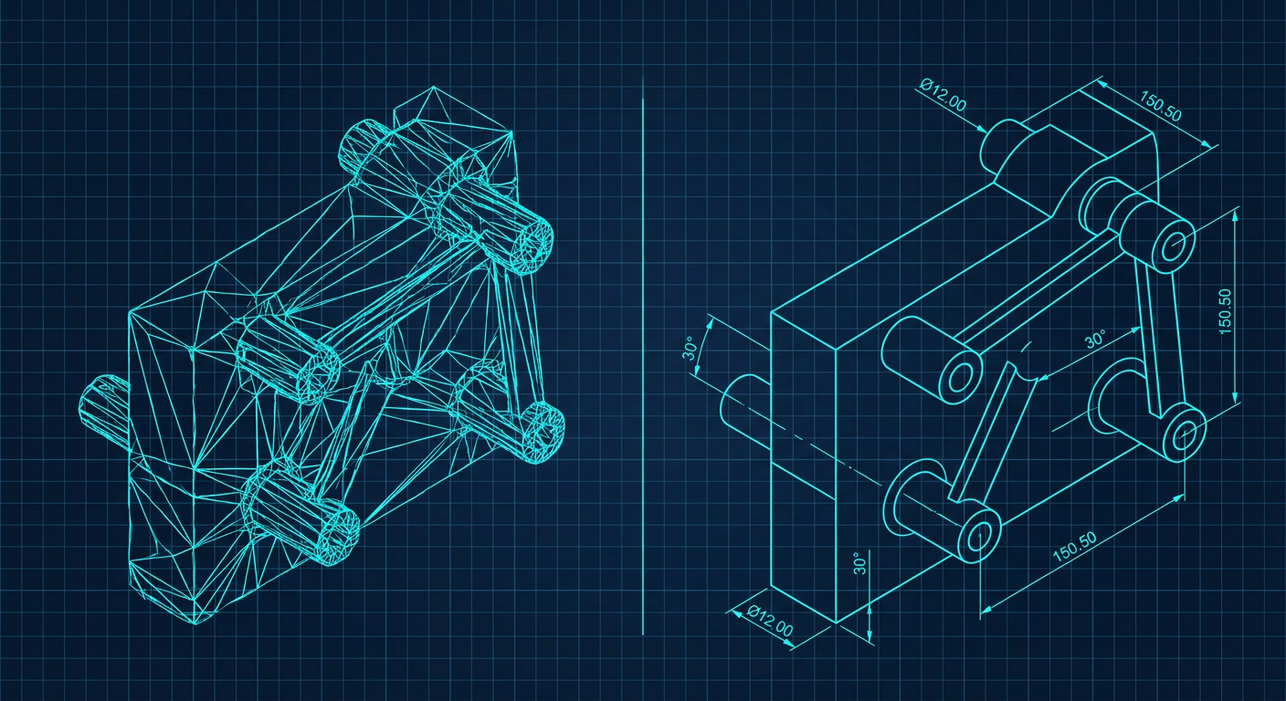
In early March 2026, researchers out of Fudan University released FutureCAD, an architecture designed to tackle one of generative design's most persistent headaches: getting large language models to ground their operations in actual boundary representation primitives rather than just spitting out disconnected program code. Around the same time, tools across the text-to-CAD ecosystem, from Zoo.dev to BuildCAD and Leo AI, rolled out updates claiming closer parity with traditional parametric modelers.
For a mechanical engineer or robotics shop owner, these developments sound promising on paper. You type a prompt for a four-bar clevis mount or a planetary carrier, and seconds later a 3D solid appears on your screen. You download a STEP file. It looks clean in the preview viewer.
Then you drop that file into your CAM package to program a three-axis mill, or you try to mate a flanged needle roller bearing into its bore inside SolidWorks. Everything grinds to a halt.
The bore is not an analytical cylinder. It is a faceted collection of 128 micro-planar faces stitched together with arbitrary vertex tolerances. Your CAM toolpath generator cannot find a center axis for a circular interpolation cycle. The assembly solver cannot assign a concentric mate because there is no true mathematical cylindrical surface, only an approximated polyhedral boundary. What looked like a five-minute automation shortcut just turned into a two-hour manual remodel.
This is the B-Rep gap. Until generative CAD tools solve the fundamental mathematical difference between surface visualization and topological boundary representation, text-to-CAD remains a tool for industrial designers making visual mockups, not mechanism engineers building parts that move and mate under load.
The Difference Between Geometry That Looks Right and Geometry That Machines
Computer graphics and mechanical engineering solve two completely different problems. Rendering engines care about what light does when it hits an exterior shell. They use polygonal meshes, which are networks of triangles defined by vertices, edges, and normal vectors. A high-density mesh with 500,000 polygons looks smooth to the human eye. To a graphics shader, it is cheap to compute and easy to manipulate.
To a CNC machine or a coordinate measuring machine (CMM), a mesh is dead data. A milling spindle does not move along an approximation of a circle. It runs an arc command (G02 or G03) based on a defined center point, a starting radius, and a sweep angle. If you feed a faceted cylinder into an automated toolpath routine, the controller attempts to generate thousands of tiny linear G01 moves. The machine jerks, cycle times balloon, tool wear spikes, and the resulting bore finish fails an H7 tolerance check before you even take the part off the fixture.
Mechanical CAD kernels like Parasolid, ACIS, and Open CASCADE do not store shapes as collections of flat triangles. They use Boundary Representation (B-Rep). A B-Rep model consists of two distinct layers: topology and geometry.
+-------------------------------------------------------------+
|                        B-REP MODEL                          |
+-------------------------------------------------------------+
                               |
        +----------------------+----------------------+
        |                                             |
        v                                             v
+-----------------------+                 +-----------------------+
|       TOPOLOGY        |                 |       GEOMETRY        |
|  (Relational Graph)   |                 | (Exact Analytical Math)|
+-----------------------+                 +-----------------------+
| Shells                |                 | Surfaces:             |
| Faces                 | <-------------> |  Planes, Cylinders,   |
| Loops                 |   Boundaries    |  Cones, Tori, NURBS   |
| Edges                 |   and Trims     | Curves:               |
| Vertices              |                 |  Lines, Circles,      |
+-----------------------+                 |  Ellipses, B-Splines  |
+-------------------------------------------------------------+
The geometry layer defines the exact underlying mathematical equations for surfaces and curves. A planar face is an exact plane equation with infinite extent. A cylindrical face is an exact radius revolving around an infinite axis vector.
The topology layer acts as the bounding graph. It defines vertices (points in space), edges (trimmed segments of parametric curves), loops (closed circuits of edges), faces (trimmed regions of geometric surfaces), and shells (closed sets of faces that bound a manifold solid).
When you build a part in a real CAD tool, every feature operation edits this topological graph while maintaining strict Euler-Poincaré characteristics. If a generative system generates arbitrary vertex coordinates without enforcing topological manifold rules, the downstream kernel rejects the solid. You cannot fillet an edge if the topological graph does not recognize two adjacent faces sharing a single, continuous analytical curve.
Why LLMs Stumble on the Topological Naming Problem
Most modern text-to-CAD systems work by using a large language model to write code in a programmatic CAD script, such as CadQuery, OpenSCAD, or proprietary API calls into a geometry kernel. The LLM translates a natural language prompt into a sequential script: create sketch, draw circle, extrude boss, select face, cut hole.
This workflow succeeds on primitive geometry: a rectangular block with a centered hole. It collapses as soon as you design a functional mechanism requiring dependent secondary operations, such as bearing retaining ring grooves, lead-in chamfers, draft angles, and dynamic pivot points.
The collapse happens because of the transient topological naming problem.
When a human designer adds a 0.5 mm chamfer to the inner lip of a bore, they click the circular edge created by the previous cut-extrude operation. In the background, the CAD kernel assigned that edge an internal persistent identifier when it calculated the boolean intersection between the cylinder and the top face.
An LLM writing code from scratch has no visibility into what transient edge names or face IDs will exist after the kernel executes line 14 of its script. If the LLM guesses an index, such as selecting edges()[4] from a list, any minor tweak to a preliminary sketch dimension can re-index the edges. The chamfer attaches to the wrong feature, the boolean union fails, or the script crashes with a null pointer error.
The FutureCAD benchmark paper (Li et al., March 2026) documented this exact limitation. Standard text-to-code pipelines show a severe drop in success rate when moving from simple primitive extrusions to operations that require B-Rep primitive grounding, such as fillets, draft angles, and concentric offsets.
Generative CAD Fidelity and Feature Execution Benchmark
The following data summarizes the experimental results reported by Li et al. (arXiv:2603.11831, 2026), evaluating how state-of-the-art CAD generation pipelines handle complex B-Rep geometry and secondary operations compared against standard text-to-CAD program generators.
| Pipeline / Method | Overall Reconstruction Accuracy (%) | Secondary Operation Execution Rate (Fillets/Chamfers) (%) | Invalid Geometry / Non-Manifold Rate (%) | Mean Topological Graph Deviation Score |
|---|---|---|---|---|
| Standard Text-to-CAD Code Generation | 77.65 | 31.40 | 22.35 | 3.56 |
| CAD-Translator Baseline | 79.08 | 34.12 | 20.92 | 3.86 |
| B-Rep Primitive Grounded (FutureCAD) | 94.23 | 82.60 | 5.77 | 1.90 |
Receipts: Metrics compiled from Li et al. (2026), Section 6, evaluating execution integrity across sequential parametric modeling steps requiring transient face and edge selections.
Notice the secondary operation execution rate for standard text-to-CAD generators: barely 31 percent. Nearly seven out of ten times an AI attempts to apply a basic functional feature like a chamfer or a fillet to an existing solid, it fails because it cannot resolve the transient topological reference. For a mechanism designer needing precise shaft steps and stress-relieving fillets on a high-speed linkage, a 31 percent success rate is useless.
The Kinematic Reality: Why Assemblies Cannot Mate Mesh Junk
If single parts suffer from missing B-Reps, assemblies completely disintegrate. A mechanism is not an isolated lump of metal. It is a system of constrained degrees of freedom.
Consider a simple double-wishbone suspension upright. To be usable in an engineering workflow, that upright requires:
- Two spherical ball joint mounting tapers with precise center-to-center distances.
- A pair of co-axial cylindrical bearing bores with an internal shoulder maintaining perpendicularity within 0.012 mm.
- Caliper mounting lugs with flat, coplanar datum faces parallel to the wheel plane within 0.025 mm.
- A steering arm tie-rod pickup point with a defined kinematic pivot point relative to the kingpin axis.
When you import a true B-Rep STEP file into an assembly environment, your mates rely on analytical geometry. A concentric mate aligns the infinite centerline vectors of two analytical cylinders. A coincident mate locks two infinite planar surfaces together. An angular limit mate tracks the dihedral angle between two distinct planes through a range of motion.
+-------------------------------------------------------------+
|                  ASSEMBLY SOLVER CONSTRAINT                 |
+-------------------------------------------------------------+
                               |
      +------------------------+------------------------+
      |                                                 |
      v                                                 v
+----------------------------+     +----------------------------+
|     TRUE B-REP STEP        |     |      AI MESH / FACET       |
+----------------------------+     +----------------------------+
| - Exact cylinder axis      |     | - No continuous centerline |
| - Analytical plane vector  |     | - Normal varies per facet  |
| - Deterministic clearances |     | - Zero contact surface     |
| - Clean multi-body kinematics|   | - Solver fails to converge |
+----------------------------+     +----------------------------+
      |                                                 |
      v                                                 v
  SUCCESS: Deterministic Pin Mate      FAILURE: Kinematic Singularity
If you feed an AI-generated model that was converted from a polygonal mesh into this assembly solver, the solver fails. A faceted bore contains no central axis vector. To mate a pin into that hole, you must manually construct a reference 3D sketch, sample three points on the faceted surface, fit a circle through them, extrude a construction axis, and use that derived axis for your joint.
By the time you finish building reference planes and surrogate datums for every pivot point on an eight-link mechanism, you could have modeled the entire assembly from scratch in native parametric CAD.
Tolerancing, Fits, and the Disappearance of Feature Trees
A solid model without an editable feature tree is what engineers call a dumb solid. Even if a generative tool outputs a mathematically valid B-Rep STEP file, losing the parametric feature tree destroys your ability to perform tolerance stack-up analysis.
In standard engineering practice, you do not model a nominal 20 mm shaft as 20.000 mm and call it a day. You define an ISO fit: an h6 shaft (20.000 mm to +0.000/-0.009 mm) running inside an H7 bore (20.000 mm to +0.021/-0.000 mm) for a sliding fit, or an s6 fit for a press fit into a rotating hub.
+-------------------------------------------------------------------------+
|                    BEARING FIT TOLERANCE BREAKDOWN                      |
+-------------------------------------------------------------------------+
| Feature                 | Target Fit | Nominal | Machined Limits        |
+-------------------------+------------+---------+------------------------+
| Rotor Shaft OD          | ISO h6     | 20.0 mm | 19.991 mm / 20.000 mm  |
| Inner Bearing Race Bore | Press Fit  | 20.0 mm | 20.002 mm / 20.008 mm  |
| Resulting Interference  | +0.002 mm to +0.017 mm (Deterministic Retain) |
+-------------------------------------------------------------------------+
| AI Mesh Output Variance | Arbitrary Polyhedral Drift: +/- 0.150 mm      |
| Result on Shop Floor    | Scrap part: bearing slips or splits housing   |
+-------------------------------------------------------------------------+
In a parametric model, you click the sketch dimension, change the nominal drive diameter, update your tolerance annotations, and the entire downstream model updates automatically. Keyways, snap ring grooves, and seal faces stay attached to their parent datums.
In an AI-generated dumb STEP file, the feature history is gone. The bore is a fixed surface in space. If physical testing reveals that thermal expansion during operation causes the bearing to bind, you cannot simply update an equation parameter. You must apply direct modeling cuts, offset surfaces manually, or re-prompt the generative AI and hope it does not arbitrarily alter the wall thickness, mounting bolt circle, or clevis width while recalculating the shape.
Direct modeling on dumb solids is acceptable for minor draft adjustments on injection-molded plastic enclosures. It is unacceptable for precision kinematic mechanisms where a 0.05 mm shift in pivot position changes the mechanical advantage, stroke length, and torque curve of a robotic actuator.
A Five-Point Evaluation Rubric for Generative Mechanical Tools
Before your engineering team invests time integrating any generative CAD tool into your production pipeline, run the tool through this shop-floor verification checklist. If the software fails any of these five tests, its output belongs in the concept rendering pile, not on your machining schedule.
1. The True Cylinder Test
Generate a mounting block with a 25.0 mm through-bore. Export the file as a STEP or IGES solid and open it in your standard CAD package.
- Pass: The CAD measure tool selects the inner diameter as a single continuous surface, displays the radius instantly, and identifies a center axis vector.
- Fail: The measure tool forces you to select individual segmented facets or interprets the bore as a collection of trimmed B-spline patches with varying radii.
2. The Datum Plane Retention Check
Prompt the tool to generate a symmetric linkage arm with three non-parallel pivot bosses.
- Pass: The model includes origin-grounded orthogonal planes (XY, YZ, ZX) and co-planar boss faces that can serve as primary datum features (Datum A) for GD&T callouts.
- Fail: The model is tilted at an arbitrary compound angle in 3D space with no planar reference surfaces, requiring you to construct reference geometry before measuring parallelism or runout.
3. The Secondary Operation Stress Test
Ask the system to add a 1.5 mm radius fillet along an intersection curve between a conical flange and a prismatic rib, followed by an internal retaining ring groove inside a bore.
- Pass: The tool executes the fillets and cuts cleanly without self-intersecting loops or micro-gaps between adjacent surfaces.
- Fail: The model generates zero-thickness geometry, naked edges, or fails to compute the boolean difference where the groove intersects the internal wall.
4. The Mated Joint Convergence Test
Import two generated mechanism components (such as a clevis and a rod end) into an assembly solver. Apply a concentric mate between the pin holes and a coincident mate between the thrust faces.
- Pass: The solver resolves instantly with one remaining rotational degree of freedom. You can drag the rod end through its full angular sweep without solver singularities or constraint errors.
- Fail: The solver reports over-constrained or conflicting conditions because the thrust faces are out-of-square by fractions of a degree, or the bore centers are skewed.
5. The Downstream CAM Feature Recognition Test
Load the generated part into your CAM package (such as Fusion 360 CAM, Mastercam, or Hypermill) and run automatic feature recognition for hole drilling and 2D contouring.
- Pass: The CAM engine automatically groups identical bolt patterns, recognizes tap drill depths, and assigns standard drilling cycles (G81/G83) to holes.
- Fail: The CAM engine detects no standard hole features and forces you to manually select 3D boundary curves for every single pocket and hole on the part.
What This Means for Mexaio AI
At Mexaio AI, we reject the notion that mechanical design is a text prompt that produces a static 3D picture. True mechanism engineering starts with kinematics, constraints, and dynamic simulation, not raw shapes.
Our platform focuses on generating parametric, editable, and simulation-checked mechanisms where every joint, clearance, and structural rib retains its engineering provenance. Instead of dead polygonal geometry or ungrounded program guesses, we build design systems that respect B-Rep topology, preserve parametric feature history, and maintain direct compatibility with the physical realities of CNC machining, bearing fits, and multi-body dynamics.
Direct Answer: Why Text-to-CAD Fails on the Shop Floor
Text-to-CAD fails in mechanical production because natural language models generate faceted surface meshes or ungrounded geometry scripts rather than mathematically exact Boundary Representation (B-Rep) solids. This absence of analytical cylinders, planar datums, and persistent topological feature trees makes the output impossible to mate in kinematic assemblies, incompatible with automated CAM toolpaths, and incapable of holding standard ISO machining tolerances.
Where Mechanism Designers Go from Here
Generative technology in mechanical design will eventually mature, but that maturation will not come from scraping more 3D meshes off the internet to train bigger diffusion models. It will come from integrating large language models and reinforcement learning agents directly into programmatic, constraint-based geometry engines that understand transient topology and kinematic constraints.
Until that integration becomes standard across commercial text-to-CAD tools, keep a sharp boundary in your engineering office. Use prompt-driven mesh generators for early industrial design brainstorming, aesthetic styling reviews, and rough customer mockups.
When it comes time to cut aluminum, size a spline, or verify that a four-bar linkage clears an actuator bracket across its entire 90-degree operating stroke, demand native parametric B-Reps. Test your tools with the five-point rubric, inspect your cylindrical centerlines, and never send an unconstrained facet to a CNC spindle.
Sources
- Li, J., Zhang, Q., Chen, Q., Qiu, G., Lou, Y., & Zhou, X. (2026). Towards High-Fidelity CAD Generation via LLM-Driven Program Generation and Text-Based B-Rep Primitive Grounding. arXiv:2603.11831: https://arxiv.org/html/2603.11831v2
- Zoo.dev. Zookeeper Conversational CAD Agent and ML CAD Model Generation: https://zoo.dev/zookeeper
- Leo AI. AI-Generated CAD Models: Why Most Aren't Ready for Production: https://www.getleo.ai/blog/ai-generated-cad-models-production-guide
- Tech Soft 3D. What is Boundary Representation (B-Rep)?: https://www.techsoft3d.com/resources/blog/what-is-boundary-representation-b-rep-/
- Shapr3D. Boundary representation (B-Rep): What it is, and why it's a problem in CAD: https://www.shapr3d.com/content-library/what-is-b-rep
- BuildCAD AI. Text to CAD: Describe a Part, Get an Editable CAD Model: https://buildcad.ai/text-to-cad