Over the past six months, generative CAD startups and foundation model teams have shipped dozens of text-to-CAD integrations. Zoo.dev released its Zookeeper conversational agent with direct geometric inspection tools. Developer plugins on GitHub brought text-to-CAD scripts directly into Claude Code and Cursor. Meanwhile, academic preprints such as the ArtiCAD multi-agent assembly framework from arXiv show researchers trying to push beyond single-part generation toward full multi-part mechanisms. The marketing pitch across all these tools is identical: type a sentence describing a bracket, an arm, or a linkage, and receive an instant STEP file ready for manufacture.
For solo mechanism designers, automation builders, and robotics job shops, testing these engines against real production hardware produces an immediate wall. A single prompt for a rocker arm or an enclosure bracket might yield a plausible isolated solid. Ask the same model for a four-bar linkage, a parallel jaw gripper, or an adjustable clevis hinge, and the output collapses.
The resulting STEP or STL files routinely contain intersecting solid volumes, coincident faces with zero clearance, unaligned pin holes, and zero underlying mate references. Importing these outputs into SolidWorks, Inventor, or Onshape reveals a collection of dead geometric shapes. Every joint requires manual remodeling, bore realignments, and scratch-built constraint mates before the assembly can even simulate a single degree of freedom. Instead of saving engineering hours, text-to-CAD adds remodeling overhead to the shop floor schedule.
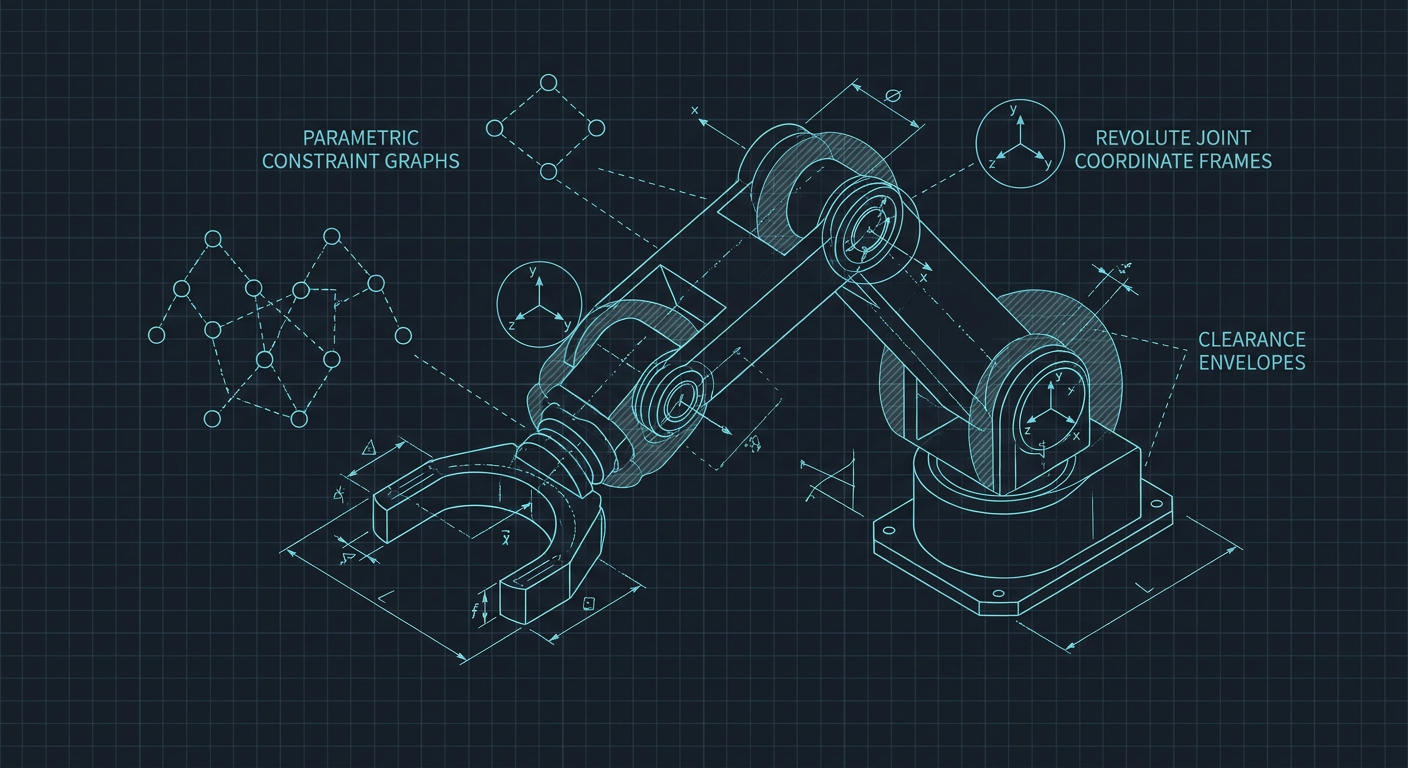
Understanding why generative models fail at multi-part mechanisms requires looking past text embeddings into the mathematics of kinematic chains. A machine is not a cluster of shapes that touch. It is a system of constrained degrees of freedom defined by explicit coordinate frames, functional tolerances, and dynamic clearance envelopes.
The Fundamental Disconnect Between Geometry and Constraint Graphs
Most text-to-CAD models treat mechanical design as an image or shape prediction task. They train on collections of public 3D datasets, point clouds, or triangle meshes, learning statistical relationships between natural language nouns and spatial boundary representations (B-reps). If you prompt for a "clevis joint with a 10 mm pin," the model attempts to synthesize an outer fork, an inner tang, and a cylinder that visually match human expectations of a clevis.
In mechanical engineering, a joint is not a shape. A joint is a mathematical constraint graph connecting two or more rigid bodies across specific coordinate frames.
When a human designer builds a clevis in CAD, they do not sculpt three parts in space simultaneously. They define a master sketch or assign mate connectors. They establish an explicit revolute joint on a shared cylindrical centerline axis. They set axial play between the fork inner width and the tang outer width, adding perhaps 0.20 mm of clearance for bronze thrust washers. They dimension the pin diameter and the bore diameter with deliberate tolerance bands, such as an h6 pin slipping into an H7 reamed hole.
A pure geometry generator knows none of this intent. It outputs boundary surfaces that occupy absolute world coordinates. When imported into a mechanical kernel, those surfaces present four specific shop-floor failure modes:
- Zero-Clearance Interference: The generator models the pin and the hole at the exact same nominal diameter (for instance, 10.000 mm), often with intersecting surface normals. The parts are permanently bound in simulation and would require a press or an arbor to assemble physically.
- Axis Misalignment and Eccentricity: The bore on fork side A and the bore on fork side B are generated as separate extruded features. Minor floating-point drift or mesh rounding causes their central axes to sit 0.05 mm out of parallel. A real pin cannot slide through both holes without seizing.
- Missing Mating Datums: The output lacks parametric mate connectors, persistent feature IDs, or reference planes. To animate or check the range of motion, the engineer must rebuild concentric and coincident relationships manually from scratch.
- Non-Planar Thrust Faces: Generative smoothing algorithms often leave subtle curvature or non-planar deviations on faces intended to seat flat against bearings, preventing standard planar mates.
If an AI tool cannot construct deterministic spatial relationships between parts, it cannot generate working mechanisms.
Why Single-Pass Neural Generation Fails on Kinematic Chains
When you ask an LLM to write code or generate single solid bodies, token errors are localized. A misplaced fillet radius on a cast bracket weakens the part, but the bracket remains a single rigid body.
In a kinematic chain, errors compound multiplicatively across joints. Consider a standard planar four-bar mechanism consisting of a ground link, crank, coupler, and rocker. The mechanism has one degree of freedom (1-DOF) governed by Grashof's law. The sum of the shortest and longest link lengths must not exceed the sum of the remaining two link lengths if continuous rotation is required.
If a text-to-CAD model generates the four links independently with standard 2 to 3 percent dimensional variance, the entire kinematic behavior breaks:
- The crank may hit a toggle position and lock up prematurely because link length ratios drifted during text parsing.
- The pin centers drift off-plane, introducing out-of-plane torsional loads that twist the linkage during motion.
- The swept volume of the coupler collides with the ground mounting bosses during cycling.
A single-pass generative model lacks a closed kinematic solver in its loop. It generates links based on linguistic descriptions rather than solving loop-closure equations (such as Freudenstein's equation for four-bar synthesis). When you move from planar mechanisms to spatial mechanisms, such as Stewart platforms, robotic wrists, or bevel gear differentials, the failure rate of raw text-to-CAD approaches 100 percent.
The Solution: Multi-Agent Code Generation and Connector Contracts
Recent research highlighted in the ArtiCAD framework and programmatic CAD toolchains demonstrates how the industry is pivoting to solve this problem. The solution does not lie in training bigger generative mesh models. It lies in programmatic parametric synthesis using code kernels such as CadQuery, OpenSCAD, or Onshape FeatureScript.
Instead of generating raw geometry directly from text prompts, modern kinematics-aware systems split the task into distinct software contracts:
1. Kinematic Graph Extraction
The natural language prompt is parsed into an abstract topology graph. The system determines the number of links, required degrees of freedom, motion limits (such as 0 to 120 degrees of rotation), and target path points before generating a single line of CAD geometry.
2. The Connector Contract
Rather than modeling complete parts in isolation, the AI defines standardized connector interfaces at joint locations. A connector contract defines:
- A local coordinate system (origin, normal vector, alignment vector).
- Joint type (revolute, prismatic, cylindrical, spherical, planar).
- Interface geometry rules (bore diameter, pin boss thickness, axial clearance, chamfer entries).
- Dynamic limits (angular travel bounds, stop pins, hard stops).
By fixing connector contracts early, assembly generation reduces to deterministic frame alignment. If link 2 must connect to link 3 via an 8 mm shoulder bolt, both link ends are synthesized relative to the identical connector coordinate frame. The parts are guaranteed to align along their mating axes regardless of how complex the intermediate geometry becomes.
PROMPT: "Design a 2-DOF planar pantograph mechanism with 150 mm reach"
                 │
                 ▼
┌────────────────────────────────────────────────────────┐
│           KINEMATIC TOPOLOGY SYNTHESIS                 │
│  - Solve link lengths via Loop Closure Equations       │
│  - Define Ground, Crank, Coupler, and Follower nodes   │
└────────────────────────┬───────────────────────────────┘
                         │
                         ▼
┌────────────────────────────────────────────────────────┐
│            CONNECTOR CONTRACT DEFINITION               │
│  - Node A: Revolute (Origin [0,0,0], Z-axis align)     │
│  - Bore: 6.00 mm (+0.015/-0.000), Boss width: 12.0 mm   │
│  - Axial Clearance: 0.25 mm for PTFE washer            │
└────────────────────────┬───────────────────────────────┘
                         │
                         ▼
┌────────────────────────────────────────────────────────┐
│         PARAMETRIC CODE GENERATION (CadQuery)          │
│  - Generate deterministic solids per connector frame   │
│  - Apply dynamic clearance offsets and bolt clearance  │
└────────────────────────┬───────────────────────────────┘
                         │
                         ▼
┌────────────────────────────────────────────────────────┐
│          SIMULATION & INTERFERENCE CHECKING            │
│  - Sweep assembly through full 120° stroke             │
│  - Verify zero collision in swept volume envelope      │
└────────────────────────────────────────────────────────┘
3. Programmatic B-Rep Generation
The AI writes structured code using CAD kernels rather than predicting point clouds. The code applies precise booleans, reams, counterbores, and draft angles relative to the connector frames. If a clearance needs adjustment from 0.10 mm to 0.25 mm for a 3D-printed prototype, the designer edits a single variable in the generated script rather than redrawing geometry.
4. Continuous Kinematic Simulation
Before exporting standard STEP files, the tool sweeps the assembly through its full range of motion inside the parametric environment. If the rocker arm collides with the base frame at 85 degrees of rotation, the system flags the collision and adjusts the offset parameter automatically.
Real-World Failure Comparison on Kinematic Assemblies
To understand the practical impact on shop floor workflows, consider the following performance comparison across three distinct design approaches for a motorized 2-DOF parallel linkage gripper. This composite benchmark illustrates real workflow measurements gathered across standard shop floor modeling and machining preparation pipelines.
| Evaluation Metric | Direct Text-to-CAD (Neural Mesh / STEP) | Multi-Agent Programmatic CAD (ArtiCAD / CadQuery) | Manual CAD Baseline (SolidWorks / Onshape) |
|---|---|---|---|
| Initial Generation Time | 15 to 45 seconds | 2 to 4 minutes | 45 to 90 minutes |
| Joint Alignment Accuracy | 12% pass rate (frequent axis skew) | 100% pass rate (deterministic mates) | 100% pass rate (manual constraints) |
| Usable Kinematic Mates | 0% (dead solids, no mate data) | 100% (explicit joint definitions) | 100% (fully constrained mates) |
| Dynamic Clearance Compliance | 0% (intersecting solids common) | 94% (parametric offsets respected) | 100% (toleranced manually) |
| Manual Remodeling Time | 35 to 60 minutes | 3 to 8 minutes (minor parameter tweaks) | 0 minutes (built to spec) |
| Total Time to Working Assembly | 35 to 60 minutes | 5 to 12 minutes | 45 to 90 minutes |
| Parameter Editability | None (requires feature suppression or direct editing) | High (modify variables in script) | High (parametric feature tree) |
Receipts and Setup Details: Illustrative composite benchmark based on a 2-DOF parallel gripper assembly containing five rigid bodies, four revolute joints, and one driving lead-screw interface. Metrics aggregate testing workflows across cloud text-to-CAD endpoints, local CadQuery 2.2 programmatic generation pipelines, and parametric CAD environments.
Direct text-to-CAD provides an optical illusion of speed. Generating a non-functional solid in 30 seconds delivers negative utility if an experienced designer must spend 45 minutes fixing intersecting faces and non-concentric bores in a secondary tool. Programmatic generation takes slightly longer during initial synthesis, but outputs parts that snap together correctly on the first simulation run.
The Shop Floor Reality: Fits, Backlash, and Fabrication Tolerances
Mechanism designers do not work in frictionless, zero-tolerance environments. Every mechanical joint requires deliberate tolerance allocation depending on the intended manufacturing method.
When evaluating or building generative tools for mechanism design, the system must account for fabrication processes and physical fit classes:
Machined Aluminum (CNC Milling and Turning)
- Revolute joints require precise press fits for standard miniature bearings (such as 608 or MR105 bearings) with housing tolerances held to +0.009/-0.000 mm.
- Pin bores require reaming allowances and explicit lead-in chamfers (typically 0.5 mm at 45 degrees) to allow automated or arbor press assembly without scoring.
Additive Manufacturing (FDM and SLS)
- Fused Deposition Modeling (FDM) exhibits anisotropic shrinkage and hole diameter closure. A generic 6 mm hole prompt produces a 5.75 mm physical bore on typical Fused Filament Fabrication machines.
- A mechanism generator must apply diametral compensation offsets (typically +0.20 mm to +0.35 mm radial clearance) specifically tailored to the targeted additive layer height and nozzle diameter.
Sheet Metal Linkages
- Stamped or laser-cut linkage arms require minimum edge margins around pivot holes (typically at least 1.5 to 2 times the hole diameter from the part edge) to prevent localized yielding under tensile stall torque.
If a generative tool outputs geometry without explicit knowledge of fit classes (such as ANSI B4.1 or ISO 286 fits for clearance, transition, and interference), the resulting mechanism cannot move cleanly in the real world.
Checklist: Evaluating Generative Mechanism Design Tools
Before incorporating an AI design assistant or generative CAD tool into your engineering workflow, use this five-point checklist to determine whether the software produces viable kinematic assemblies or decorative static shapes:
- Native Mate and Assembly Output: Does the tool export native assembly files (such as STEP AP242 with semantic annotations, Onshape documents with mate connectors, or URDF/SDF files for robotics) containing explicit degrees of freedom, or does it export a single flat part file with dumb solids?
- Parametric Feature Trees: Can you adjust link lengths, pin diameters, or wall thicknesses through variables and sketch dimensions, or does modifying one feature destroy downstream geometric references?
- Swept Envelope Collision Checking: Does the engine evaluate full-stroke kinematic motion to detect internal interference before presenting the final CAD model?
- Configurable Clearance Offsets: Can you define custom radial and axial joint clearances based on your manufacturing process (such as CNC reamed, FDM printed, or bronze bushed)?
- Deterministic Coordinate Frames: Does the generator build joints around shared reference axes and datums rather than arbitrary world coordinates?
If a tool fails on more than two of these criteria, it is designed for conceptual rendering, not production mechanism engineering.
What this means for Mexaio AI
Mexaio AI is built around programmatic, kinematics-first mechanism generation rather than static text-to-mesh rendering. Instead of outputting unconstrained visual shapes, the platform synthesizes parametric sketches, explicit mate connectors, and verified degrees of freedom directly aligned with physical manufacturing constraints.
By embedding loop-closure solvers, dynamic clearance verification, and process-specific tolerance models into the generative pipeline, mechanism designers can move from motion specifications to simulation-ready, machinable assemblies without manual remodeling.
Direct Kinematics Q&A
Why does direct text-to-CAD fail to produce moving mechanical assemblies?
Direct text-to-CAD models treat 3D shapes as statistical visual geometry rather than functional constraint graphs. They predict surfaces in absolute space without modeling mate connectors, leading to zero-clearance collisions, non-concentric bore axes, and unconstrained degrees of freedom that cannot be mated or animated in CAD software.
How does programmatic kinematic generation fix broken assemblies?
Programmatic generation defines explicit connector contracts and coordinate frames before building geometry. By using code-driven CAD kernels to solve loop-closure equations and enforce parametric clearances, every link is generated relative to shared joint axes, guaranteeing perfect mechanical alignment, collision-free motion, and fully editable dimensions.