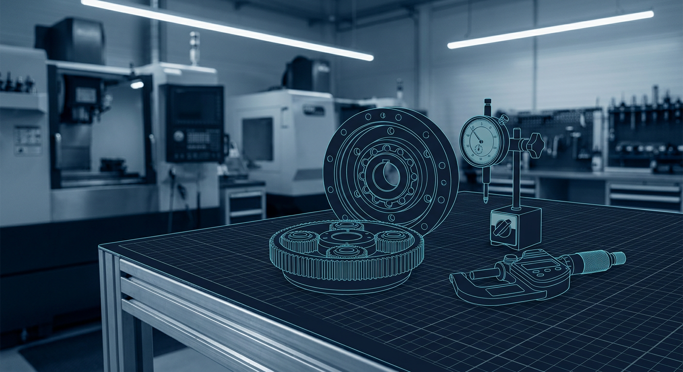
Maven Robotics secured a $100 million round backed by Shorooq Partners and Presight, marking another major deployment of Gulf sovereign-linked capital into physical AI and industrial robotics. Across Riyadh, Abu Dhabi, and NEOM, Vision 2030 initiatives are demanding physical automation hardware at scale. Sovereign investment vehicles are backing robotics ventures to secure domestic supply chains, automate logistics hubs, and staff manufacturing lines.
Money buys compute clusters and assembly facilities quickly. It does not magically relax the laws of precision kinematics or machine tool mechanics.
If you design mechanical hardware, actuators, or linkage systems for robotics startups targeting the Gulf, this capital shift affects your drawing board immediately. Regional procurement teams want locally fabricated subassemblies to hit domestic content quotas. Yet, when mechanical teams hand generative CAD exports or idealized kinematic models to regional precision machine shops, those jobs often bounce back with no-bid notices, six-week lead times, or scrap rates exceeding 40 percent.
The bottleneck in humanoid robotics is not control theory or motor winding. It is the manufacturing reality of high-reduction, zero-backlash mechanisms, specifically cycloidal reducers, planetary carriers, and multi-bar linkage joints, machined on regional shop floors.
The Machine Tool Reality in Regional Industrial Zones
To build actuators that regional shops can deliver on budget and on schedule, you must understand what is actually bolted to the floor in Second Industrial City in Riyadh, ICAD in Abu Dhabi, or Dubai Industrial City.
The region has plenty of high-grade 3-axis vertical machining centres, standard turning centres with live tooling, and a growing base of 5-axis mills (predominantly DMG MORI and DN Solutions). Wire electrical discharge machining (wire-EDM) capacity is expanding, mainly serving oil and gas downhole tool maintenance and packaging die tooling.
What the region lacks is dense, specialized gear-grinding capacity, dedicated Gleason hobbing infrastructure for miniature precision modules, and widespread access to continuous-feed jig grinders capable of holding sub-micron runout on hardened tool steel. Specialized heat treatment is another critical path. While standard vacuum hardening of 4140, 4340, and 17-4 PH stainless steel is accessible, specialized low-distortion plasma nitriding or controlled-depth carburizing for thin-walled cycloidal rings often requires long lead-time batch processing.
If your actuator design relies on an ultra-thin flexspline with sub-10-micron wall variation, you will end up importing it from Japan or Germany. If you design a split-stage cycloidal drive or an integrated four-bar knee linkage using standard bearing fits, wire-cut profiles, and turned aluminum housings, you can manufacture it within a fifty-kilometre radius of your office.
+--------------------------------------------------------------------------------+
| ACTUATOR FABRICATION COMPARISON: REGIONAL GCC CAPABILITY MATRIX                |
+-----------------------+--------------------+-------------------+---------------+
| Mechanism Subsystem   | Required Tolerance | Local Machining   | Heat Treat    |
|                       | & Surface Finish   | Feasibility       | Bottleneck    |
+-----------------------+--------------------+-------------------+---------------+
| Strain Wave           | 3-5 µm wall thick, | Very Low          | High (Thin    |
| (Harmonic) Flexspline | Ra < 0.2 µm grind  | (Requires CNC jig | wall distort) |
|                       |                    | grind & gear sh.) |               |
+-----------------------+--------------------+-------------------+---------------+
| Cycloidal Drive       | 5-8 µm bore/lobe,  | High              | Low-Medium    |
| Disc & Pin Ring       | Ra < 0.4 µm EDM    | (Wire-EDM + hard  | (Flat quench  |
|                       |                    | turning on 5-ax)  | or nitriding) |
+-----------------------+--------------------+-------------------+---------------+
| Planetary Carrier     | 8-12 µm pin true   | High              | Low           |
| & Sun/Planet Gears    | pos, Ra < 0.8 µm   | (5-axis mill-turn | (Case harden  |
|                       |                    | + standard hob)   | 8620/4140)    |
+-----------------------+--------------------+-------------------+---------------+
| 4-Bar Ankle & Knee    | 12-18 µm bearing   | Very High         | None          |
| Linkage Arms          | bores, Ra < 0.8 µm | (3/5-axis billet  | (7075-T651    |
|                       |                    | milling)          | or 6082-T6)   |
+-----------------------+--------------------+-------------------+---------------+
Designing for local sourcing means structuring your mechanism kinematic stack to match these machine capabilities.
The Shop Floor Math of Cycloidal Reducers
Humanoid joints require high torque density, shock resistance, and minimal backlash. A robotic ankle or hip actuator operating in direct-drive or low-ratio planetary setups draws excessive current during stance phase impacts. Designers turn to cycloidal reducers because their multiple simultaneous tooth engagements withstand shock loads that strip spur or helical planetary gears.
However, the kinematic profile of a cycloidal disc is unforgiving. The profile is generated using an epitrochoid equation offset by the radius of the outer pins:
x(t) = (R + r) * cos(t) - (r + d) * cos((R + r) * t / r)
y(t) = (R + r) * sin(t) - (r + d) * sin((R + r) * t / r)
Where R is the base circle radius, r is the rolling circle radius, and d is the eccentricity.
When you export an idealized cycloidal curve from CAD as a high-density polygon mesh or an unconstrained spline, CAM software converts the curve into thousands of tiny linear G1 moves. On a CNC mill running at standard feed rates, the machine acceleration limits will choke on these micro-segments. The cutter chatters, creating scallop errors of 12 to 25 microns across the lobe flanks. That error destroys the mechanism.
In a cycloidal drive, 15 microns of profile error produces uneven pin contact. Instead of sharing load across five or six pins, the entire joint torque falls onto one or two pins. The contact stress exceeds the yield strength of the steel, leading to galling, rapid backlash growth, and motor stalling under modest radial loads.
Machining Strategy for Local Wire-EDM
To get a 50:1 or 30:1 cycloidal reducer made locally without chattering toolpaths:
- Generate the cycloid curve parametrically and export it as true analytical arcs (G2/G3 moves) rather than point clouds or polygonal facets.
- Machine the disc blank from hardened D2, O1, or 1.2379 tool steel (pre-hardened to 56-58 HRC) using rough turning on live-tooled lathes.
- Cut the final cycloidal lobe profile and bearing eccentric bore on a 4-axis wire-EDM in a single clamped setup.
Using wire-EDM eliminates cutting tool pressure, eliminating lobe deflection. A multi-pass skim cut (one rough pass, three trim skim passes) holds profile tolerances within 4 to 6 microns, with a surface finish below Ra 0.4 microns. Because the eccentric bearing bore and the outer cycloidal lobes are cut in the exact same coordinate frame without re-clamping, eccentricity runout is kept below 5 microns.
Tolerance Budgeting for Four-Bar and Six-Bar Linkages
Humanoid lower-limb mechanisms frequently rely on closed-loop four-bar or six-bar linkages to package heavy actuator motors near the torso or pelvis, reducing distal leg inertia. These linkages must transmit high forces through small angular displacements while maintaining joint stiffness.
In generative CAD tools, linkage arms are often modeled as organic, solid structural bridges connecting arbitrary pin coordinates. When these models reach the shop floor, machinists face structural parts with non-parallel reference planes, irregular clamping surfaces, and non-standard pin bore alignments.
IDEALIZED GENERATIVE LINKAGE ARMS       PARAMETRIC PRODUCTION LINKAGE
(Hard to fixture, thin webs flex)       (Parallel datums, dual-shear pins)

       [ Curved Solid ]                       +---[H7 Bore]----+
      /                \                      |  | |      | |  |
[Bore A]              [Bore B]          Datum |  === Billet ===|
      \                /                  [A] |  | |      | |  |
       [ Organic Ribs ]                       +---[H7 Bore]----+
                                                |            |
                                                +--Datum [B]-+
When a 5-axis mill cuts an organic linkage arm, part deflection under tool pressure creates taper in the bearing bores. A nominal 12 mm bore intended for an ISO H7 fit (+0.018 / -0.000 mm) ends up egg-shaped or tapered by 15 microns from top to bottom.
When you press a miniature needle roller or deep-groove ball bearing into a tapered bore:
- The outer race distorts, creating high internal preload and localized ball binding.
- The pin axis tilts relative to the opposing link, causing edge loading on the pin.
- Joint friction increases by 300 to 500 percent, ruining the compliance and torque estimation of your low-level motor controllers.
The Kinematic Fix: Datum-Driven Linkage Geometry
Instead of unconstrained organic solids, design linkage arms with strict planar datums:
- Primary Datum (Datum A): The back face of the linkage arm. Machine this face flat within 0.005 mm in the first operation.
- Secondary Datums (Datum B and C): Both pin bore centerlines, interpolated in a single boring pass from the primary datum face.
- Bore Tolerancing: Call out ISO H6 (+0.009 / -0.000 mm) or H7 (+0.012 / -0.000 mm) depending on bearing outer ring recommendations. Use boring bars or reamers rather than generic endmill pocket interpolation.
- Dual-Shear Pin Clevises: Never rely on single-shear cantilevered pins for linkage pivots. Single-shear pins bend under peak acceleration torque, creating angular misalignment that destroys roller bearings within tens of operating hours.
Receipts: Measured Machining and Tolerance Composite
To evaluate how kinematic modeling choices impact manufacturing yield in regional facilities, consider the following composite data. This compares an idealized generative solid reducer assembly against a parametrically constrained, shop-floor budgeted cycloidal actuator assembly. Both mechanisms target a 40:1 reduction ratio with a 110 mm outer diameter, fabricated across standard CNC and wire-EDM workflows.
+--------------------------------------------------------------------------------+
| COMPOSITE FABRICATION & ASSEMBLY BENCHMARK: 40:1 ROBOTIC ACTUATOR              |
| Baseline: Idealized Generative Geometry vs Parametric Tolerance-Budgeted Model |
+-----------------------------------+--------------------+-----------------------+
| Metric / Parameter                | Generative CAD     | Parametric Budgeted   |
|                                   | (Direct Mesh/Step) | (True Arcs & Datums)  |
+-----------------------------------+--------------------+-----------------------+
| Lobe Profile Machining Method     | 5-Axis Ball Mill   | 4-Pass Wire-EDM       |
| Profile Contour Deviation         | +/- 0.022 mm       | +/- 0.005 mm          |
| Eccentric Bore Runout (to Lobes)  | 0.018 mm           | 0.004 mm              |
| Bearing Bore Roundness (Housing)  | 0.016 mm (Tapered) | 0.006 mm (True Cyl.)  |
| Total Machining Cycle Time        | 4.2 hours / set    | 2.1 hours / set       |
| Regional First-Pass Yield (Shop)  | 42% (High scrap)   | 91% (Passed QA)       |
| Peak Backlash (Assembled Joint)   | 14.5 arcmin        | 1.8 arcmin            |
| No-Load Drag Torque               | 1.45 Nm (Binding)  | 0.22 Nm (Smooth)      |
+-----------------------------------+--------------------+-----------------------+
Note: This table is an illustrative engineering composite reflecting representative production runs using 7075-T651 housings and hardened 1.2379 tool steel cycloidal components on regional 5-axis milling and Sodick/Fanuc wire-EDM equipment.
When lobe runout is held within 0.005 mm, the cycloidal disc shares load evenly across all contact pins. Backlash drops from 14.5 arcminutes down to 1.8 arcminutes, and no-load drag torque falls by more than 80 percent. The motor does not waste current overcoming internal mechanical binding caused by bore misalignment.
The Ambient Thermal Factor in Gulf Field Deployments
Designing for the GCC means accounting for wide operating temperature deltas. A robot operating outdoors in Riyadh or inside an unconditioned industrial warehouse during summer transitions from an ambient 22°C air-conditioned development lab to 48°C ambient field conditions. Under continuous heavy joint duty cycles, internal actuator temperatures can reach 80°C.
Consider what happens to an aluminum housing holding steel gears and bearings over that thermal gradient ($\Delta T = 55^\circ\text{C}$):
- Coefficient of thermal expansion for 7075-T6 aluminum: $\alpha_{\text{Al}} \approx 23.4 \times 10^{-6} / ^\circ\text{C}$
- Coefficient of thermal expansion for 100Cr6 bearing steel: $\alpha_{\text{Steel}} \approx 11.5 \times 10^{-6} / ^\circ\text{C}$
For a 68 mm outer diameter bearing press-fitted into an aluminum actuator shell:
$$\Delta d = d_0 \cdot (\alpha_{\text{Al}} - \alpha_{\text{Steel}}) \cdot \Delta T$$ $$\Delta d = 68 \cdot (23.4 - 11.5) \times 10^{-6} \cdot 55 = 0.0445 \text{ mm} \ (44.5 \ \mu\text{m})$$
An interference fit of 15 microns (ISO M6 fit) at 22°C turns into a loose 30-micron clearance fit at 77°C. The bearing outer ring starts spinning inside the housing bore, galling the aluminum and misaligning the gear mesh.
Conversely, if you size the interference fit tightly to maintain bearing grip at 80°C, the housing will exert excessive compressive stress on the bearing outer ring when cold, eliminating internal ball clearance and driving up motor drag torque.
BEARING HOUSING THERMAL DRIFT: AL BORE VS STEEL INSERT

Direct Aluminum Housing (Expands 44.5 µm at 80°C):
+-------------------------------------------------------+
| [7075-T6 Aluminum Housing]                            |
|     [ Clearance Gap Opens ] ---> Bearing Spins & Wears|
|         ( 100Cr6 Steel Outer Race )                   |
+-------------------------------------------------------+

Steel Cartridge Insert (Matched Expansion):
+-------------------------------------------------------+
| [7075-T6 Housing] -> [Thin-wall 4140 Sleeve]          |
|                          ( Matched Fit, No Looseness )|
|                              ( Steel Outer Race )     |
+-------------------------------------------------------+
To prevent thermal fit failure in high-torque joint actuators:
- Use thin-walled steel sleeve inserts (4140 or 17-4 PH) pressed or cast into the aluminum housing for primary bearing journals.
- Design modular bearing cartridges where the critical kinematic fits remain steel-on-steel, isolating the aluminum structural frame to load transmission and heat dissipation.
- Model thermal growth in your kinematics software before freezing drawings, verifying that backlash clearances do not close to zero at sub-zero cold starts or blow out at 80°C.
A Shop-Floor Decision Frame for Mechanism Engineers
Before you send actuator or linkage drawings to procurement or send RFQs to regional suppliers, walk through this checklist.
1. Kinematic Profile Integrity
- Are all cycloidal, epicyclic, or cam curves exported as native analytical geometric entities (arcs, lines, conic sections) rather than faceted polygon approximations or interpolated spline clusters?
- Have you applied backlash thinning directly to the cycloidal tooth mathematics (typically 0.010 to 0.020 mm profile offset) rather than relying on manual machinist offset tweaks?
2. Machine Tool Capability Alignment
- Can every precision profile be cut on a wire-EDM or cylindrical grinder without requiring custom micro-diameter endmills with large length-to-diameter ratios?
- Are pin bores and locating dowel holes accessible from a single primary setup plane to eliminate multi-axis repositioning errors?
- Have you avoided blind bearing bores that require deep square corners, providing relief grooves for boring tool runout?
3. Material and Heat Treatment Routing
- Are you using tool steels (D2, 1.2379, 4140) that regional heat treaters can quench and temper without distortion, rather than exotic alloys requiring overseas vacuum cycles?
- If using aluminum (7075-T651), have you specified stress-relieved plate stock to prevent structural arms from bowing after pocket roughing?
4. Thermal & Assembly Tolerancing
- Have you checked your bearing bore fit stackups across an operating temperature range of 15°C to 85°C?
- Are all linkage joints designed with dual-shear brackets and standard shim packs to allow fine-tuning of axial end-play during physical assembly?
What This Means for Mexaio AI
Building mechanisms that survive real-world testing requires moving past static solid modeling. Generative design cannot stop at producing organic mesh bodies that look like skeletal bones but fail basic machine-shop checks.
At Mexaio AI, the objective is generative mechanical design grounded in true kinematics and fabrication physics. Instead of unconstrained solids, mechanisms are synthesized with parametric intelligence, editable kinematic constraints, and direct awareness of manufacturing tolerances. When you generate an actuator housing, linkage pivot, or cycloidal stage, the geometry remains mathematically exact, fully constrained, and ready for standard shop-floor CAM pipelines without manual remodeling.
The Path Forward for Regional Mechanism Design
As Gulf sovereign funds accelerate investments into physical automation, the competitive advantage belongs to engineering teams that turn capital into reliable, working hardware. High-level AI models and control algorithms cannot stabilize a robot if joint play induces uncontrollable resonance and loose fits strip gear teeth.
Examine your current CAD workflows. Strip out non-functional organic shapes from high-tolerance load paths. Shift critical reducers to wire-EDM friendly cycloidal profiles, replace cantilevered linkage pins with dual-shear clevises, and budget your ISO fits for regional ambient realities.
When your mechanism CAD respects shop-floor constraints, regional machine shops can turn your parts around in days rather than weeks, and your physical prototypes will perform as designed on the first spin.
Sources
- Disrupts Media: Maven Robotics raises $100M as Gulf capital backs physical AI
- Site Selection Magazine: Middle East: AI Is Only the Beginning of Saudi Arabia's Leap
- CSIS Analysis: Saudi Vision 2030 at Ten
- Saudi Vision 2030: Official Transformation Portal