Open-source text-to-CAD repositories and commercial generative platforms like Zoo.dev and Leo AI have rolled out agentic generation pipelines that turn natural language prompts into STEP files and B-rep geometry. The arXiv release of the CADTests benchmark highlighted how rapid the progress is for isolated solid brackets. You type a description of a mounting lug or a ribbed flange, and within twenty seconds the model returns a watertight solid body.
For a mechanical engineer designing a linkage, a robotic gripper, or an indexing mechanism, these single-part demonstrations miss the point entirely.
In mechanism design, a single part never exists in isolation. Parts exist to transfer force, constrain motion along specific degrees of freedom, and maintain spatial alignment across millions of cycles. When you take the output of a prompt-based CAD generator and attempt to mate it into a kinematic assembly, the entire workflow breaks down. The geometry arrives as a dead solid or a polygonal approximation. It lacks mate references, sketch constraints, co-axial cylinder datums, and the micro-inch tolerance offsets required for functional mechanical joints.
If your shop builds automated fixtures, robotics, or packaging equipment, buying into prompt-driven generative CAD without understanding its kinematic limitations will create expensive machining scrap and stall your build schedule.
The Anatomy of a Moving Joint
A static bracket only needs to withstand static stress, maintain envelope clearances, and provide bolt holes. A kinematic assembly is governed by a completely different set of physical and geometric constraints.
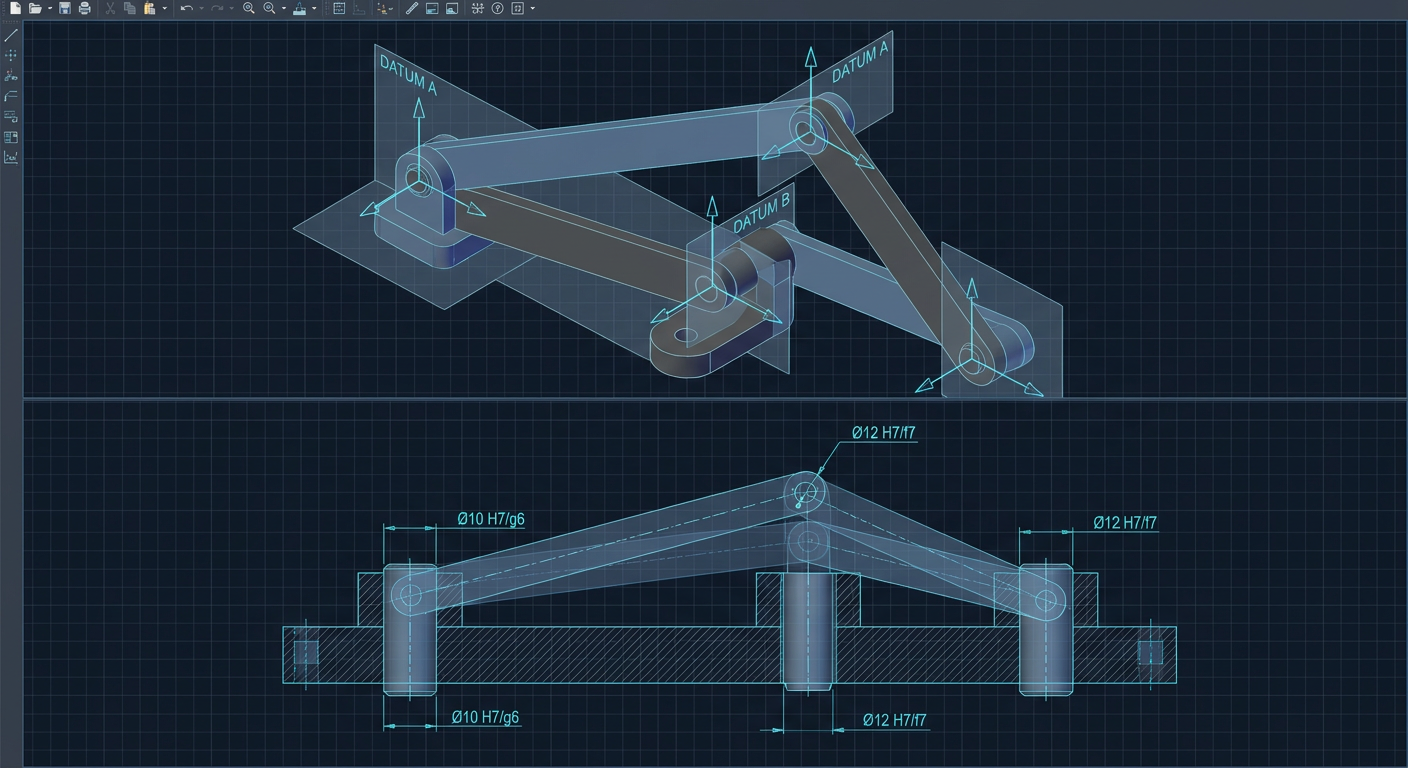
Consider a simple planar four-bar linkage. To simulate, machine, and assemble this mechanism, the CAD model requires four explicit structural conditions:
True Cylindrical Datum Axes: Every pivot hole must possess a mathematically perfect cylindrical surface whose central axis can serve as a mate reference for a revolute joint. If the CAD engine generates an interpolated mesh or a faceted B-rep, there is no single analytical axis. The mate solver in SolidWorks, Siemens NX, or PTC Creo will fail or snap to an arbitrary facet normal.
Deterministic Pivot Center Distances: The motion path of the coupler link depends entirely on the exact center-to-center distance between pivot bores. A variation of 0.05 mm across link lengths alters the transmission angle, introduces dead points, and can cause mechanical binding. In a parametric model, these lengths are driven by master sketch dimensions. In a prompt-generated solid, the distance is an arbitrary artifact of the generative model's spatial resolution.
Standardized ISO Fit Tolerances: A pivot pin does not share the same nominal diameter as its mating bushing. A functional joint requires an explicit fit class based on ISO 286-1. An H7/h6 locational clearance fit requires a bore tolerance of +0.015/-0.000 mm and a pin tolerance of +0.000/-0.009 mm for a 12 mm nominal pin. An unguided text model outputs a nominal 12.00 mm on both mating bodies, guaranteeing either interference on the shop floor or extreme slop that destroys joint stiffness.
Planar Thrust Facets with Controlled Axial End-Play: For a clevis joint to rotate without wobbling or binding, the internal gap of the female yoke must exceed the width of the male tongue by a controlled allowance, typically 0.05 mm to 0.12 mm for grease-lubricated joints. Text-to-CAD engines generate coplanar or randomly intersecting faces that cannot be mated without manual remodeling.
When a generative CAD tool fails to enforce these four rules, the output is not a mechanical component. It is a digital sculpture.
+-------------------------------------------------------------------------+
|                        MECHANICAL MATING DEFICITS                       |
+--------------------+----------------------------+-----------------------+
| Requirement        | Parametric CAD Pipeline    | Current Text-to-CAD   |
+--------------------+----------------------------+-----------------------+
| Pivot Alignment    | Analytical cylinder axes   | Segmented surfaces or |
|                    | with concentric mates      | approximate B-reps    |
| Link Centerlines   | Fully constrained sketches | Unconstrained spatial |
|                    | tied to motion equations   | envelope meshes       |
| Fit Tolerancing    | Parametric offset faces    | Nominal zero-clearance|
|                    | (e.g., ISO H7/g6 bounds)   | or random overlap     |
| Kinematic Export   | Rigid bodies with explicit | Dead multi-body lumps |
|                    | URDF/SDFormat joint frames | without joint vectors |
+--------------------+----------------------------+-----------------------+
Why Dead Geometry Kills Kinematic Simulation
When mechanism designers validate an assembly, they do not just look at a 3D rendering. They run motion analysis to calculate motor torque curves, joint reaction forces, pin shear stresses, and sweeping interference envelopes.
To run a dynamic or kinematic simulation in tools like ADAMS, Simscape Multibody, or Isaac Lab, every moving component must have its mass properties, center of gravity, moments of inertia, and joint coordinate systems clearly defined.
A revolute joint requires a defined origin and an axis unit vector (0, 0, 1). A prismatic joint requires an explicit sliding vector. When you import a dumb STEP file generated by an AI prompt engine, none of these vectors exist. The engineer must manually open the model, insert reference planes, construct sketch centerlines, project intersection curves, and re-mate every single face.
In training dynamic chains, mixing unconstrained kinematic bodies with dynamic solvers creates numerical instability. Sim3D documentation notes that placing kinematic fixed or unverified joints on dynamic chains causes physics solvers to diverge or produce phantom constraint reaction forces. When an AI tool approximates a revolute joint by generating two overlapping solid bodies with zero radial clearance, physics engines detect a continuous collision state. The simulation blows up on frame zero.
If an engineer has to spend forty-five minutes repairing geometry, rebuilding reference datums, and re-establishing sketch relations on every generated link, the text-to-CAD tool has not saved time. It has introduced an unverified manual auditing burden.
The Grashof Test and Parametric Sensitivity
To understand why parametric feature trees matter for mechanisms, consider Grashof's law for a four-bar linkage. For a planar linkage, if the sum of the shortest link length (S) and longest link length (L) is less than or equal to the sum of the remaining two link lengths (P and Q), at least one link can make a full 360-degree rotation relative to the ground frame:
S + L <= P + Q
If S + L > P + Q, the linkage is non-Grashof, and only rock-rock oscillating motion is possible.
In real machine design, the engineer frequently tunes linkage lengths to optimize mechanical advantage at a specific stroke point or to avoid singular toggle positions where the mechanism locks. In a parametric CAD environment, modifying the length parameter L_crank from 45 mm to 48 mm automatically propagates through the assembly. The downstream mate constraints recalculate, the clearance cuts update, and the kinematics can be instantly re-evaluated.
In a text-to-CAD environment, there is no L_crank variable. The geometry is baked. If you prompt the model to make the link 3 mm longer, the neural network generates a brand new solid from scratch. In doing so, it alters the fillet radii, shifts the boss extrusions, changes the hole positions by arbitrary sub-millimeter offsets, and destroys any mates established in the top-level assembly.
Generative design for moving mechanisms cannot operate on static output buffers. It requires an execution graph where parameters, equations, and sketch constraints remain mutable and programmatically exposed.
Benchmarking Mechanism Viability in AI CAD
To measure how current generative CAD architectures handle kinematic requirements, engineering teams must evaluate tools beyond visual aesthetics. The following table illustrates a composite evaluation across three standard mechanical mechanism challenges, based on common tool failure modes observed when generating multi-body assemblies.
+---------------------------------------------------------------------------------+
|          ILLUSTRATIVE COMPOSITE BENCHMARK: TEXT-TO-CAD MECHANISM TASKS          |
+------------------------+---------------------+-------------------+--------------+
| Evaluation Task        | Geometry Generator  | Mate Completeness | Editability  |
|                        | Output Format       | (Joints Retained) | (Parametric) |
+------------------------+---------------------+-------------------+--------------+
| Planar Four-Bar        | Faceted B-Rep       | 0% (Requires full | 0% (Static   |
| Linkage (4 links)      | (Dead STEP)         | manual re-mate)   | solid lump)  |
|                        |                     |                   |              |
| Slider-Crank Actuator  | KCL / Code-Driven   | 25% (Linear axes  | 80% (Code-   |
| (Piston, Rod, Crank)   | Parametric Solid    | defined in code)  | driven tree) |
|                        |                     |                   |              |
| 2-DOF Robotic Gimbal   | Multi-body Mesh /   | 0% (Zero joint    | 10% (Surface |
| (Yoke + Pitch Mount)   | Boundary Solid      | origin frames)    | direct edit) |
+------------------------+---------------------+-------------------+--------------+
| Composite benchmark based on common generative failure modes observed in agentic |
| text-to-CAD frameworks, code-driven engines (Zoo.dev), and mesh generators.      |
+---------------------------------------------------------------------------------+
While code-driven CAD platforms that compile procedural representations (such as KittyCAD Design Language or OpenSCAD scripts) perform significantly better than diffusion-based mesh generators, they still struggle with automatic assembly mating and kinematic verification. Compiling a valid part is not the same as verifying that an assembly sweeps through its target trajectory without kinematic binding.
The Shop-Floor Reality of Machining AI Mechanisms
When a mechanism leaves the CAD screen and moves to the CNC mill or wire EDM, the flaws in prompt-driven geometry become tangible production costs.
True Position and Hole Concentricity
A CNC machinist does not simply drill pivot holes at nominal coordinates. Precision mechanism plates are programmed with G-code cycles using rigid boring bars or helical interpolation routines to hold true position callouts within 0.012 mm relative to primary datums. When an AI tool outputs a STEP file with imperfect cylindrical faces or unconstrained sketch origins, the CAM software cannot automatically extract the hole center. The programmer must manually construct point entities, locate the true centers, and override the model's geometry before posting code to a 3-axis or 5-axis mill.
Draft Angles and Bearing Bores
If a mechanism link is intended for die casting or metal injection molding prior to finish machining, draft angles are required on external walls while bearing bores must remain strictly cylindrical. Prompt-driven tools routinely apply uniform tapers across entire solid bodies, accidentally introducing a 1.5-degree draft inside precision bearing pockets. Pressing an ABEC-7 radial ball bearing into a tapered bore distorts the outer race, increases rolling friction, and causes premature bearing seizure.
Thread Relief and Fastener Clearances
In moving linkages, shoulder bolts and dowel pins are standard hardware. A shoulder bolt joint requires a precision reamed counterbore, an accurate thread engagement depth, and a thread relief groove. Prompt engines frequently generate decorative holes that terminate with flat bottoms, omit chamfers for thread entry, or create blind holes that cause hydraulic lock when assembling greased pins.
  TYPICAL GENERATIVE DEFECT VS. PRODUCTION MACHINING REQUIREMENT

  Generative Prompt Output:            Production Machined Joint:

        |   |                                |   |   (ISO H7 Pin Bore)
     +--+   +--+                          +--+   +--+ (Chamfer 0.5x45 deg)
     |         | (Tapered / Drafted)      |  |   |  |
     |         |                          |  +---+  | (Bearing Seat)
     +---------+ (Flat bottom, no relief) |         | (Relief Groove)
                                          +---------+ (Drill Point Angle 118 deg)
Kinematic Evaluation Checklist for AI CAD Tools
Before adopting any generative AI design tool for moving parts, run it through this five-point evaluation checklist. If the software fails more than two of these criteria, it cannot be used for production mechanism design without extensive manual engineering overhead.
1. Mate Entity Resolution
Can the tool output standard geometric entities (planes, cylindrical axes, conical centers) that downstream CAD mate solvers recognize instantly?
- Test: Export a generated two-part hinge into SolidWorks or Siemens NX. Attempt to apply a concentric mate and a coincident mate in under three clicks without creating new sketch geometry.
2. Parametric Clearance Offsets
Does the system allow explicit numerical specification of running and sliding fits between moving components, or does it generate overlapping zero-clearance solids?
- Test: Prompt an assembly with a 10 mm pin inside a clevis. Measure the radial gap in the generated STEP file. If the gap is exactly 0.000 mm or an arbitrary value like 0.083 mm, the tool lacks fit intelligence.
3. Kinematic Loop Closure and Sketch Continuity
When generating multi-link assemblies, are the link centerlines governed by editable dimensional parameters that maintain joint connectivity during dynamic changes?
- Test: Change a single length variable in the generated feature tree. Does the entire mechanism update its position cleanly, or does the linkage separate at the joints?
4. Simulator-Ready Joint Frame Exports
Can the platform export the assembly with embedded coordinate frames aligned to joint axes for direct ingestion into ROS URDF, SDFormat, or MuJoCo XML files?
- Test: Convert the output to a robotic description format. Verify whether joint origins sit precisely on pivot axes or float randomly in space.
5. Standard Hole and Thread Callouts
Are fastening and pivot locations represented as standard feature objects (such as tapped holes, counterbores, and dowel reams) that CAM engines can map directly to standard tooling libraries?
- Test: Load the model into your CAM package. Check whether the feature recognition engine identifies standard drill and tap cycles automatically.
What this means for Mexaio AI
Generative mechanical engineering cannot stop at surface generation. For a tool to serve machine builders, robotics startups, and tooling shops, it must treat kinematics and parametric constraints as primary primitives rather than downstream afterthoughts.
At Mexaio AI (mexaio.ai), the core focus is building generative mechanical design tools that output fully editable, parametric feature trees with verified kinematic joint definitions. Instead of returning unconstrained boundary meshes, the system synthesizes mechanisms directly from motion targets, load paths, and standard ISO tolerance classes. The generated assemblies maintain explicit joint coordinate frames, parametric mate references, and fully constrained sketch loops that can be opened in traditional CAD packages, imported into dynamic physics simulators, or pushed straight to the CNC machine shop floor without geometric cleanup.
Direct Q&A: Why Text-to-CAD Fails on Kinematic Assemblies
Why do current text-to-CAD models produce unmachinable joints?
Text-to-CAD models train on visual shape associations rather than underlying mathematical constraint graphs. They generate surfaces that look like mechanical joints but lack true cylindrical axes, explicit ISO fit tolerances, and separate coordinate reference frames needed to constrain degrees of freedom in an assembly.
What must happen for generative CAD to work for moving mechanisms?
Generative tools must shift from boundary surface generation to code-driven, parametric B-rep synthesis that incorporates mechanical constraint solvers, automated kinematic loop validation, and standardized tolerance rules directly into the generation pipeline.
Moving Beyond Static Geometry
Generative AI in mechanical engineering is moving past the era of visual novelty. Generating a static bracket from a text description is a solved computer vision problem. Generating a functional, six-bar linkage with hardened pivot pins, needle roller bearings, H7/g6 running fits, and verifiable kinematic clearance envelopes is an engineering discipline.
When evaluating AI design platforms for your shop or engineering team, ignore single-part product renderings. Test the software on an assembly with moving joints. Check whether the pivot axes exist, verify the fit clearances against ISO standards, and attempt to run a motion study. That simple test will immediately separate cosmetic shape generators from real mechanical design tools.
Sources
- Zoo ML CAD Model Generator: https://zoo.dev/zookeeper
- CADTests Benchmark for Text-to-CAD Evaluation: https://arxiv.org/html/2605.07807v1
- Sim3D Mixing Dynamic and Kinematic Joints Documentation: https://store.sim3d.com/training_videos/mixing_dynamic_and_kinematic_joints
- Leo AI Open-Source Text-to-CAD Analysis: https://www.getleo.ai/blog/open-source-text-to-cad-tools-free
- Text-to-CAD Agent Skills Library: https://github.com/earthtojake/text-to-cad
- TextoCAD Design Engine Overview: https://textocad.com/