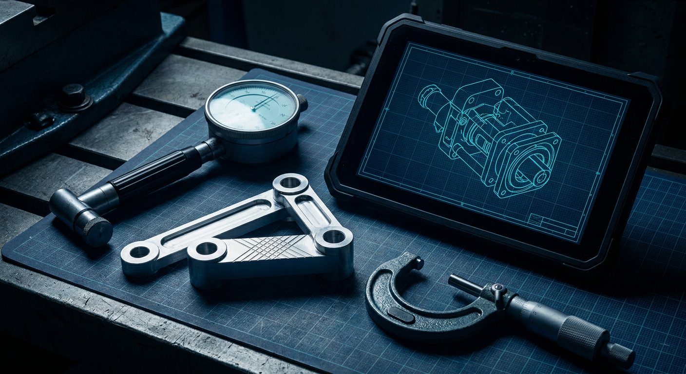
The Shift from Meshes to Solids Has Not Solved Machinability
Over the past six months, text-to-CAD engines have shifted their marketing pitch. Platforms like Zoo.dev, Leo AI, and TextoCAD moved beyond generating raw, triangulated STL meshes. They now produce native Boundary Representation (B-rep) solids, editable feature scripts, and STEP files that open directly in SolidWorks, Inventor, or Onshape. Developers are hooking CAD generation engines into Claude Code and custom Model Context Protocol servers to emit procedural solids from short plain-text prompts.
For a mechanical designer trying to build a four-bar linkage, an actuated robotic gripper, or a compact gearbox housing, getting a clean B-rep model from a sentence sounds like genuine progress. You prompt for an aluminum pivot bracket with two 8 mm dowel bores spaced 45 mm apart, download a STEP file, and drop it into an assembly. The solid has clean cylindrical faces, sharp planar steps, and recognizable chamfers.
Then the drawing goes to the machine shop.
Once that generated model reaches a CNC mill or a wire EDM cell, the workflow hits a wall. The part fails inspection, the bearings refuse to press in, or the mechanism binds after three degrees of rotation. The problem is not that the AI failed to produce solid geometry. The problem is that solid geometry is only a fraction of what makes a mechanism work. Text-to-CAD systems treat 3D parts as spatial volumes. Production engineering treats them as chains of datum references, geometric tolerances, and kinematic constraint graphs.
When you bypass constraint graphs in favor of prompt-driven geometry, you trade thirty minutes of CAD sketch setup for days of toolroom rework and scrapped billet.
The Difference Between Nominal Shapes and Engineering Fits
Every CAD model generated by an AI prompt is a nominal model. If you ask for an 8 mm bore, the engine creates an exact mathematical cylinder with a diameter of 8.000 mm. If you ask for a matching steel pin, the engine produces a nominal 8.000 mm shaft.
In pure mathematics, that pin fits inside that hole. In a physical machine shop, that combination is undefined.
In real mechanical assemblies, an 8 mm hole can mean half a dozen completely different manufacturing operations depending on its role in the kinematic chain:
- A clearance hole for an M8 socket head cap screw, which should be drilled to 9.0 mm (ISO medium clearance) with a loose location tolerance.
- A close-running bearing pivot, requiring an ISO H7/g6 or H8/f7 clearance fit, where the bore is reamed to +0.015 / -0.000 mm and the shaft is ground to -0.005 / -0.014 mm to allow free rotation with lubricating oil.
- A light press fit for an 8 mm deep-groove ball bearing outer ring, which demands an H7 or J7 bore (+0.015 / -0.000 mm or +0.010 / -0.006 mm) with surface roughness held under Ra 0.8 micrometers to prevent fretting.
- An interference location pin fit (ISO H7/p6), where the pin is 0.009 to 0.024 mm larger than the bore, requiring a thermal soak or hydraulic press for installation.
Text-to-CAD engines have no native understanding of these distinctions because they do not understand what the feature does in the kinematic stack. As TexoCAD noted in their analysis of AI tolerances, two identical-looking holes in an engine housing have completely different manufacturing requirements based on their assembly function. Shape alone does not dictate engineering tolerance.
When an AI model generates a nominal 8.000 mm bore on both sides of a clevis joint, the CNC programmer or CAM specialist has to guess what the designer intended. If the machine operator bores both holes to 8.000 mm nominal on a Haas VF-2, your nominal 8.000 mm ground dowel pin will gall and lock up on assembly. If you are fitting a sintered bronze bushing, the tight bore will crush the inner diameter, pinching the pivot shaft and stalling the motor.
+---------------------------------------------------------------------------------------------------------+
|                                 THE NOMINAL VS TOLERANCE BOUNDARY GAP                                   |
+-----------------------+---------------------------------------+-----------------------------------------+
| Feature Type          | Text-to-CAD Nominal Output            | Physical Shop-Floor Requirement         |
+-----------------------+---------------------------------------+-----------------------------------------+
| Pivot Pin Bore        | Cylindrical face at Ø8.000 mm exact   | H7 Reamed Bore: Ø8.000 to Ø8.015 mm     |
| Mating Pivot Pin      | Cylindrical face at Ø8.000 mm exact   | g6 Precision Shaft: Ø7.986 to Ø7.995 mm |
| Result on Assembly    | Interference: Metal-on-metal galling  | 0.005 to 0.029 mm sliding clearance     |
+-----------------------+---------------------------------------+-----------------------------------------+
| Dual Clevis In-Line   | Two distinct coaxial features modeled | Single GD&T Feature: Ø0.012 mm True     |
| Shaft Alignment       | without mutual position reference     | Position at MMC to Common Datum A-B     |
| Result on Assembly    | Pin binds across dual bearings        | Smooth rotation across full stroke      |
+-----------------------+---------------------------------------+-----------------------------------------+
Why Joint Datums Cannot Be Inferred from B-Rep Geometry
The fundamental breakdown between text-to-CAD and kinematic mechanisms lies in the concept of the Datum Reference Frame (DRF).
In standard 3D modeling, coordinate space is arbitrary. A CAD package has an origin point (0,0,0) and three default planes (XY, XZ, YZ). An AI text-to-CAD tool typically generates features by picking arbitrary planar sketches and extruding or revolving them relative to that internal world origin.
In geometric dimensioning and tolerancing (GD&T) under ASME Y14.5 or ISO 1101, a datum is not an origin point in space. A datum is a theoretically exact reference plane, line, or axis derived from a physical feature on the actual manufactured part. Datums establish how the part is physically mounted, how it locates against mating components, and how its motion is constrained.
Consider a precision robotic arm linkage. The critical relationship is not the distance from the top face to the world origin. The critical relationship is the parallelism and runout between the primary pivot bore (Datum A) and the secondary driven bore (Datum B).
When a machinist sets up a 3-axis or 5-axis mill to cut that linkage, they do not reference the arbitrary CAD world origin. They probe Datum A, establish an active work coordinate system on that centerline, and machine Datum B in a single clamping setup to maintain a true position tolerance within 0.02 mm.
Text-to-CAD tools do not generate datum schemes. They generate isolated boundary patches that close into a solid. Because there is no datum reference frame inside the generated STEP file, there is no metadata telling downstream CAM tools or coordinate measuring machines (CMM) how features relate to one another.
If the AI generates a split-yoke clevis, it models the left ear and the right ear as two separate features. In the CAD file, both holes might share a nominal axis. But without a datum callout establishing them as a continuous coaxial feature with a runout tolerance relative to the mounting face, a machine shop will drill the two holes from opposite setups. The resulting 0.05 mm angular misalignment will bind any rigid pivot shaft you try to slide through.
The Asymmetric Tolerance Trap on the CNC Floor
Even when engineers attempt to salvage text-to-CAD geometry by applying manual dimensional overrides, they run directly into the asymmetric tolerance trap.
Most modern CNC CAM software (such as Autodesk Fusion CAM, Mastercam, or Siemens NX CAM) can generate toolpaths directly from solid model surfaces. To machine high-tolerance features efficiently without manual offsets on every single toolpath, CAM systems rely on the 3D model being drawn at mean tolerance.
If a bearing bore is specified on an engineering drawing as:
Diameter 28.000 mm (+0.021 / -0.000 mm)
The actual target machining dimension is not 28.000 mm. The target dimension is 28.0105 mm (the exact median of the tolerance band). An experienced toolroom programmer will set toolpaths to cut the feature to the nominal CAD surface, assuming the CAD surface represents the median.
Text-to-CAD engines model strictly at the lower boundary or the nominal integer. When a prompt asks for a "28 mm bearing pocket," the engine models a 28.000 mm pocket. If the CAM programmer cuts that nominal geometry directly, the entire batch of parts will come off the machine undersized. If the tool wears by just 5 micrometers during a production run of 4140 pre-hardened steel housings, the bore drops below 28.000 mm, turning every finished piece into scrap.
To make text-to-CAD models production-ready, a designer or CNC technician must manually open the model, suppress features, rebuild sketches, offset every cylindrical face by its specific fit offset, and re-export the STEP file. At that point, the supposed speed advantage of text prompting disappears entirely.
Workflow Benchmark: Text-to-CAD vs Parametric Kinematic Synthesis
To understand where the hours actually go when designing moving mechanical parts, consider the workflow for producing a custom dual-pivot rocker arm for a suspension linkage. The part requires two precision bearing seats (6001-2RS, 28 mm OD), an 8 mm ground shoulder bolt pivot, and a structural web that clears a rotating cam profile.
The following table represents an illustrative composite comparison based on standard toolroom operating workflows, typical machine shop CAM preparation steps, and standard CMM inspection setups.
+---------------------------------------------------------------------------------------------------------+
| WORKFLOW BENCHMARK: 2-PIVOT ROCKER ARM DESIGN AND PRODUCTION PREPARATION                              |
| Setup: Aluminum 7075-T6, 3-Axis CNC Mill, 2x 6001 Bearing Fits (H7), 1x Shoulder Bolt Pivot (f7)        |
+------------------------------------+----------------------------------+---------------------------------+
| Workflow Step                      | Text-to-CAD + Manual Cleanup     | Parametric Kinematic Synthesis  |
+------------------------------------+----------------------------------+---------------------------------+
| Initial Geometry Generation        | 45 seconds (Prompt to STEP)      | 12 minutes (Parametric sketch)  |
| Establishing Kinematic Centers     | 15 minutes (Re-sketching datums) | 0 minutes (Defined by linkage)  |
| Offsetting Fits to Mean Tolerance  | 25 minutes (Manual face offsets) | 2 minutes (Fit table driven)    |
| Adding GD&T Datum Scheme           | 20 minutes (Manual drawing prep) | 4 minutes (Integrated MBD/DRF)  |
| CAM Toolpath Generation Time       | 35 minutes (Manual overrides)    | 10 minutes (Direct feature CAM) |
| CMM Inspection Setup Time          | 30 minutes (Re-indexing datums)  | 10 minutes (Automated by DRF)   |
| First-Article Scrap Probability    | High (40% risk of bore binding)  | Low (< 5% tool wear risk only)  |
+------------------------------------+----------------------------------+---------------------------------+
| Total Engineering Prep Time        | 125.75 minutes                   | 38.0 minutes                    |
+------------------------------------+----------------------------------+---------------------------------+
While the initial 3D shape appears almost instantly with a text prompt, the downstream labor required to inject missing engineering intent makes the overall process more than three times slower than starting with a constraint-aware parametric model.
The Friction Point: Kinetic Constraint Graphs vs Spatial Envelopes
Why can't large language models or diffusion-based geometry engines simply learn GD&T and tolerances from massive datasets of mechanical drawings?
The answer comes down to representation.
Language models work on token sequences and probabilistic associations. When an AI engine generates a CAD script, it predicts what lines of code (such as OpenSCAD, CadQuery, or Parasolid API calls) usually follow a given text prompt. It knows that brackets have mounting holes, that motor mounts have bolt circles, and that clevises have cross-bores.
Mechanisms, however, are governed by graph theory and kinematics, not statistical appearance. A mechanism is a system of rigid bodies connected by kinematic pairs (revolute, prismatic, spherical, or planar joints) that restrict specific degrees of freedom.
In a kinematic constraint graph:
- Nodes represent physical rigid links with specific mass, center of gravity, and stiffness properties.
- Edges represent kinematic constraints with defined clearances, backlash allowances, and rotation limits.
- The geometry of the part is a consequence of the constraint graph and the required motion envelope, not the other way around.
Text-to-CAD approaches the problem backward. It generates the spatial envelope first, leaving the kinematic constraints undefined. When you ask a text engine to generate a scissor linkage, it gives you a shape that resembles a scissor linkage. But if the distance between link centers is off by 0.12 mm, or if the mounting face is not perfectly perpendicular to the pivot axis within 0.01 mm, the mechanism will physically lock when assembled with real bearings.
Real mechanisms cannot tolerate statistical approximation. A 0.02 mm error on a 100 mm link length changes the mechanical advantage, shifts the cycle timing, and creates secondary bending moments on pivot pins that lead to premature fatigue failure.
The Mechanism Designer Triage Rubric
Text-to-CAD is not completely useless in a mechanical design office, but using it successfully requires knowing exactly where it helps and where it introduces risk.
Use this rubric before letting prompt-generated CAD touch your production pipeline:
1. Safe for Text-to-CAD (Speed without Machining Risk)
- Low-risk mounting brackets with standard loose-clearance holes (M3, M4, M5 with ±0.5 mm clearance).
- Sensor enclosures and cosmetic protective shrouds where boundary dimensions have generous clearances (> 1.0 mm).
- Rapid rough spatial mockups used exclusively to verify component packaging envelopes in an early assembly.
- Additive manufacturing fixtures and 3D-printed wire routing clips where compliant plastic absorbs dimensional variation.
2. High Risk: Requires Complete Manual Re-Modeling
- Bearing housings and bearing blocks (any feature requiring H7, J7, or K7 tolerances).
- Multi-joint kinematic linkages, four-bar linkages, and slider-crank assemblies where pin alignment governs mechanism binding.
- Dowel-located tooling plates and fixture bases that interface with CNC machine tables.
- Dynamic sealing faces, O-ring grooves, and rotating shaft interfaces where surface finish and groove depth govern fluid leakage.
- Splines, keyways, and press-fit drive hubs where asymmetric torque transmission requires zero backlash.
If a part has moving contact surfaces, dynamic loads, or press fits, treating a prompt-generated B-rep as a finished model is a direct path to scrap.
                                  MECHANISM DESIGN TRIAGE
                                             │
                               Does the component have moving
                              kinematic joints or press fits?
                                             │
                              ┌──────────────┴──────────────┐
                              ▼                             ▼
                             YES                            NO
                              │                             │
                 Does the part require CNC                  │
               machining to tight tolerances?               │
                              │                             │
                     ┌────────┴────────┐                    │
                     ▼                 ▼                    ▼
                    YES                NO          Are clearances loose
                     │                 │          (> 1.0 mm envelope)?
                     │                 │                    │
                     │                 │             ┌──────┴──────┐
                     │                 │             ▼             ▼
                     │                 │            YES            NO
                     │                 │             │             │
                     ▼                 ▼             ▼             ▼
               REJECT AI B-REP    USE AI FOR     USE TEXT-TO-   REBUILD IN
               Use Parametric    ROUGH CONCEPT   CAD FREELY     PARAMETRIC
               Kinematics Only    Re-model for   (Enclosures,   CAD WITH
                                   Production      Brackets)     DATUMS
What This Means for Mexaio AI
At IDO, the mechanical design division behind Mexaio AI treats geometry as the final output of an engineering solver, not the starting point.
Instead of generating dead solid shapes from natural language descriptions, generative mechanical engineering must start with the kinematic graph: defining the degrees of freedom, the motion targets, the load paths, and the required fit classes. Once the kinematic constraints, datum reference frames, and manufacturing processes are mathematically resolved, the parametric solids generate naturally around those constraints.
This guarantees that when a bearing bore, a linkage clevis, or a slide mechanism is generated, the underlying feature tree maintains its engineering intent. The model exports not just as a static STEP file, but as an editable, simulation-checked mechanism with correct mean-tolerance offsets and valid datum schemes ready for toolroom programming.
What to Watch on the Shop Floor
If you are evaluating AI CAD tools for mechanical and mechanism design over the coming quarters, look past the initial prompt-to-model speed demos. Focus on how the tool handles downstream manufacturing data:
- Check if the tool allows you to assign specific ISO fit classes (such as H7, g6, or p6) directly to cylindrical features, or if it only produces nominal boundary surfaces.
- Verify whether the engine outputs Model-Based Definition (MBD) metadata or geometric datum reference frames, or if it leaves features disconnected in arbitrary coordinate space.
- Test what happens when you export a generated model to a CAM package: check if you have to manually rebuild sketch geometry to offset faces to the median tolerance band.
- Ensure the system provides editable parametric feature trees that let you adjust link lengths and pivot centers without breaking downstream mates in your assembly.
Until a generative CAD engine understands the difference between a loose clearance hole and an H7 bearing seat, a human mechanical designer must remain in the loop to turn dead geometry into real, working machinery.
Direct Answer: Why Text-to-CAD Fails on Mechanism Fits
Text-to-CAD tools fail on mechanism tolerances because they generate nominal geometric boundaries based on statistical language patterns rather than functional engineering constraints. A prompt-generated solid lacks a Datum Reference Frame (DRF) to define feature alignment, does not account for asymmetric manufacturing tolerances required for CNC toolpaths, and cannot infer whether an 8 mm hole is a loose clearance bore, a precision running fit, or an interference press fit. Without an underlying kinematic constraint graph, prompt-driven geometry will bind, gall, or scrap parts when manufactured.
Sources
- TexoCAD Technical Blog: https://blog.texocad.ai/posts/text-to-cad-tolerances
- Zoo Dev Generative Tools: https://zoo.dev/zookeeper
- Xometry Text-to-CAD Benchmark Testing: https://xometry.pro/en/articles/text-to-cad-tools-test/
- Leo AI Mechanical Design Engineering Analysis: https://getleo.ai/blog/text-to-cad-vs-generative-design
- The Fabricator GD&T Datum Analysis: https://thefabricator.com/thefabricator/article/testingmeasuring/why-datums-used-in-cad-should-remain-distinct-from-gdt-datum-features
- SimuTecra Manufacturing CAD Modeling Reports: https://simutecra.com/blogs/cad-modeling-mistakes-delay-manufacturing
- GD&T Basics Datum Feature Architecture: https://gdandtbasics.com/datum/
- EarthToJake Text-to-CAD MCP Library: https://github.com/earthtojake/text-to-cad