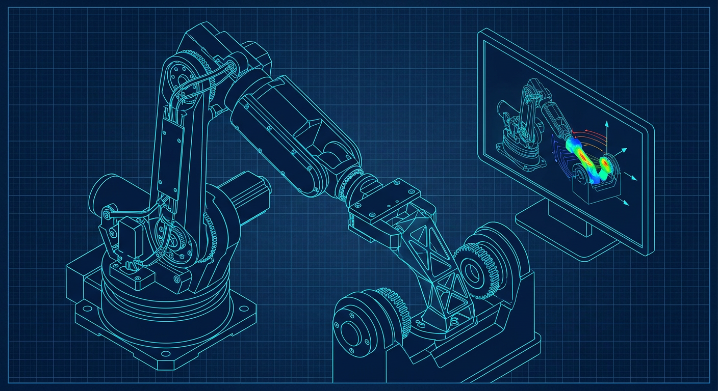
ABB Robotics and NVIDIA have detailed their partnership to integrate NVIDIA Omniverse libraries directly into RobotStudio, creating what ABB calls RobotStudio HyperReality. Slated for general release in the second half of 2026, the software targets a 99 percent sim-to-real fidelity rating and claims up to an 80 percent reduction in cell commissioning time.
For the tooling engineer, fixture builder, or mechanism designer, those headline figures sound like standard automation marketing. But the mechanical failure modes that happen during physical cell commissioning are expensive and distinctly physical. Tooling plates gouge into rotary positioners. Pneumatic cylinder end-cushions bounce unexpectedly during rapid indexing. Robot wrists fault out on over-torque because someone calculated payload inertia from a simplified CAD bounding cylinder rather than the true multi-body mass matrix.
When simulation fails to mirror reality, the machine shop pays the bill. You machine a 7075-T6 aluminum gripper bracket, send it out for hard anodizing, bolt it to an ABB IRB 6700 wrist, hook up the air lines, and watch it fault on axis 5 during an emergency stop because dynamic inertia exceeded motor torque limits. HyperReality and the GPU-driven physics engines behind it matter because they finally bring dynamic multi-body kinematics into the design loop before you cut steel.
Why Static CAD Kinematics Fail on the Shop Floor
Most CAD platforms handle kinematic motion using ideal mathematical joints. You mate a pin to a bore, define a revolute joint, drag the assembly with your mouse, and verify that the gripper fingers clear the CNC tombstone. If there is 2 mm of clearance in the assembly model, standard CAD calls it a pass.
On the plant floor, 2 mm of static clearance is a crash waiting to happen.
+--------------------------------------------------------------------------------+
| TYPICAL TOOLING SIMULATION FAILURES                                            |
+----------------------------------+---------------------------------------------+
| Static CAD Assumption            | Physical Floor Reality                      |
+----------------------------------+---------------------------------------------+
| Rigid component geometry         | Dynamic flex under 2.5G deceleration        |
| Ideal kinematic joint travel     | Backlash, bearing play, and pin deflection  |
| Zero mass for routing/tubing     | 12 mm polyurethane hoses pulling on wrists  |
| Instantaneous pneumatic stroke   | Pressure ramp-up lag and cylinder bounce    |
| Constant motor torque rating     | Thermal derating and J4/J5 singularity trips|
+----------------------------------+---------------------------------------------+
When a six-axis arm swings a 45 kg casting through a 180-degree reorientation at full acceleration, several physical phenomena occur that traditional offline programming packages ignore:
Structural Deflection: A 600 mm long cantilevered end-effector plate made from 20 mm 6061-T6 aluminum will flex under rapid deceleration. At 2.5G of deceleration, a modest tool mass creates enough bending moment to turn a 2 mm clearance gap into metal-on-metal interference.
Pneumatic Actuator Dynamics: CAD models stroke pneumatic slide units instantaneously from position A to position B. In reality, cylinder speed depends on valve flow coefficients (Cv), line length, supply pressure drops, and cylinder cushion adjustment. If a secondary clamping cylinder takes 120 milliseconds longer to lock than the digital timing chart assumed, the robot begins its exit move while the clamp arm is still sweeping through the travel zone.
Flexible Dress Packs: Robot dress packs containing high-pressure hydraulic lines, pneumatic tubing, and shielded servo cables do not stay neatly inside their neutral CAD envelopes. As the wrist rolls through axis 6, stiff bundle loops swing outward under centrifugal force, snagging on sensor brackets or fence posts that looked safe in the 3D model.
Wrist Singularity Torque Spikes: When axes 4 and 6 line up, or when axis 5 passes through zero degrees, the mathematical inverse kinematics demand infinite angular velocity from the wrist motors to maintain a linear tool tip speed. Standard CAD simulation simply steps through the trajectory. The physical robot controller throttles velocity, deviates from the programmed path, or faults on instantaneous over-current.
The Physics Engine Shift: From Kinematic Curves to Multi-Body Dynamics
Traditional robot simulation software relies heavily on geometric interpolation. You teach targets, and the software calculates interpolated spline curves between them using simplified kinematic equations.
RobotStudio HyperReality changes this workflow by tying ABB's proprietary RobotWare virtual controller directly into NVIDIA's Omniverse and Isaac simulation backends. Instead of calculating ideal joint angles, the environment runs continuous rigid-body dynamic equations, multi-point contact physics, and realistic friction models at high frequency.
+--------------------------------------------------------------------------------+
| GPU-ACCELERATED DYNAMIC SIMULATION ARCHITECTURE                                |
+--------------------------------------------------------------------------------+
|                                                                                |
|  [ ABB RobotWare Virtual Controller ] <--> [ Real-Time Kinematic Trajectory ]  |
|                         |                                                      |
|                         v                                                      |
|  [ NVIDIA Omniverse / PhysX Engine ] <---> [ Mass Matrix & Inertia Tensors ]   |
|                         |                                                      |
|                         +----------------> [ Dynamic Flex & Contact Forces ]   |
|                         |                                                      |
|                         v                                                      |
|  [ Validated Kinematic Clearance ] ------> [ G-Code Ready Tooling Geometry ]   |
|                                                                                |
+--------------------------------------------------------------------------------+
When a mechanism designer drops a custom dual-gripper assembly into this environment, the simulation does not just check for intersecting boundary surfaces. It calculates the full spatial inertia tensor of the end-effector:
$$\mathbf{I} = \begin{bmatrix} I_{xx} & I_{xy} & I_{xz} \ I_{yx} & I_{yy} & I_{yz} \ I_{zx} & I_{zy} & I_{zz} \end{bmatrix}$$
If your tooling design places heavy steel toggle clamps far out on the perimeter plate, the simulation calculates the exact off-axis moment applied to the robot's mechanical gearbox bearings during high-speed directional changes. If that dynamic load exceeds the peak torque capacity of the cycloidal reducers, the software flags the issue before you release drawings to the toolroom.
Shop Floor Verification: Measuring the Sim-to-Real Gap
To understand why this shift matters, consider how automation shops traditionally debug automated assembly stations. The following composite data represents typical physical discrepancy metrics collected across multi-axis cell commissioning projects involving custom tooling plates, rotary trunnions, and high-speed pick-and-place mechanisms.
+--------------------------------------------------------------------------------+
| COMMISSIONING DISCREPANCIES: TRADITIONAL OFFLINE CAD VS DYNAMIC DIGITAL TWIN   |
| (Illustrative Composite Data derived from standard tooling validation trials)  |
+----------------------------+--------------------+------------------+-----------+
| Metric / Failure Mode      | Standard CAD / OLP | Dynamic GPU Twin | Shop Floor|
+----------------------------+--------------------+------------------+-----------+
| Cycle Time Prediction Error| +14% to +22%       | -1.5% to +2.0%   | Baseline  |
| Dynamic Wrist Clash Errors | 3 to 6 per cell    | 0 to 1 per cell  | N/A       |
| Pneumatic Stroke Clash     | 2 to 4 per cell    | 0 per cell       | N/A       |
| Tooling Mass/Inertia Error | 18% underestimate  | < 1% error       | Baseline  |
| Commissioning Rework Hours | 45 to 80 hours     | 8 to 15 hours    | Baseline  |
+----------------------------+--------------------+------------------+-----------+
The most damaging line item on that table is commissioning rework hours. When an end-effector collides with a fixture clamp during initial floor teaching, the fix is rarely a software offset. It usually requires unbolting the tool, taking it back to the Bridgeport mill or waterjet, slotting mounting holes, cutting clearance pockets into structural gussets, or completely remanufacturing a mounting plate.
Every hour spent modifying hardened tool steel or anodized aluminum on the floor halts the commissioning crew, ties up machine shop capacity, and burns project margin.
Mechanism Synthesis: Designing for Kinematic Verification
If you want to validate multi-axis mechanisms in high-fidelity simulation environments, you cannot build CAD models the old way. Exporting a static STEP file and dumping it into a robotics tool creates dead geometry that lacks the kinematic metadata required for physics solvers.
Mechanism engineers must design assemblies as parametric kinematic chains from day one.
+--------------------------------------------------------------------------------+
| PARAMETRIC KINEMATIC MODELING PIPELINE                                         |
+--------------------------------------------------------------------------------+
|                                                                                |
|  1. Define Joint Topology (Revolute, Prismatic, Continuous Limits)             |
|                            |                                                   |
|                            v                                                   |
|  2. Assign True Material Densities (6061-T6, 4140 Steel, POM-C, Delrin)        |
|                            |                                                   |
|                            v                                                   |
|  3. Bound Actuator Envelopes (Include Pneumatic Decel & Spring Over-travel)    |
|                            |                                                   |
|                            v                                                   |
|  4. Ingest to Physics Engine (Simulate Real Motor Current & Dynamic Deflection)|
|                            |                                                   |
|                            v                                                   |
|  5. Parametric Feedback Loop (Adjust Rib Thickness / Pocket Depths in CAD)    |
|                                                                                |
+--------------------------------------------------------------------------------+
1. Joint Rigidity and True Fits
When designing custom linkages, rotary grippers, or multi-axis indexers, joint compliance must be represented accurately. An ISO H7/g6 pin fit provides smooth rotational motion on a prototype bench, but under 400 Nm of torsional shock load, minor bearing play amplifies along a 500 mm tooling arm.
In your parametric model, establish explicit coordinate systems at every pivot point. Do not rely on CAD surface coincidence mates. Define real kinematic joint limits, friction coefficients, and axial stiffness parameters so that when the robot reverses direction at top speed, the simulation exposes joint play and micro-chatter.
2. Material Density and Mass Distribution
Never leave material assignments set to default steel or generic plastic. A standard four-jaw pneumatic gripper assembly contains an aluminum body (6061-T6, 2.70 g/cm³), hardened steel guide jaws (4140, 7.85 g/cm³), and lightweight polyacetal finger pads (POM-C, 1.41 g/cm³).
If your CAD system applies a single bulk density across the assembly, the calculated center of gravity will be off by dozens of millimeters. When imported into tools like RobotStudio HyperReality or NVIDIA Isaac, that offset skews the dynamic torque vectors calculated for robot axes 4, 5, and 6, rendering the simulation useless for thermal motor checks and cycle optimization.
3. Actuator Bounds and Deceleration Buffers
When modeling pneumatic slide units or hydraulic clamp cylinders, do not model only the extended and retracted hard stops. Model the deceleration buffer zones. Standard pneumatic cylinders feature internal air cushions that engage over the final 10 mm to 20 mm of stroke.
If your tooling mechanism relies on an external shock absorber, like an Enidine or ACE miniature damper, the dynamic deceleration force must be included in the simulation. The peak deceleration force can be three times higher than the steady-state operating force, imparting sharp shock loads into your mounting brackets that can cause mechanical deflection and sensor trip errors.
Validating Custom End-Effectors: A Practical Decision Frame
Before sending a custom multi-axis tooling assembly to the CNC programming queue, run the mechanism through this five-step validation protocol.
+--------------------------------------------------------------------------------+
| TOOLING KINEMATICS VALIDATION PROTOCOL                                         |
+--------------------------------------------------------------------------------+
| [ ] STEP 1: VERIFY TRUE INERTIA TENSOR                                         |
|     - Calculate full 3x3 mass matrix including all fasteners and air fittings. |
|     - Compare calculated moments against the robot wrist load curve chart.     |
|                                                                                |
| [ ] STEP 2: CHECK DYNAMIC CLEARANCE MARGINS                                    |
|     - Run physical twin at 100% programmed speed with full payload mass.       |
|     - Maintain a minimum 25 mm dynamic clearance to account for hose whip.     |
|                                                                                |
| [ ] STEP 3: INSPECT WRIST SINGULARITIES AND FLIPS                             |
|     - Plot joint velocities across the complete path cycle.                    |
|     - Eliminate sudden 180-degree axis 4/6 reorientations during linear moves. |
|                                                                                |
| [ ] STEP 4: VALIDATE ACTUATOR TIMING AND PRESSURE DROPS                        |
|     - Apply real pneumatic stroke time curves (not instantaneous step states). |
|     - Ensure clamp confirmation switches are physically cleared before travel. |
|                                                                                |
| [ ] STEP 5: REVIEW CLAMP RIGIDITY UNDER DECELERATION                           |
|     - Evaluate grip force against 3G emergency stop inertial separation forces.|
|     - Verify that mechanical friction pads do not slip under peak cornering.   |
+--------------------------------------------------------------------------------+
What This Means for Mexaio AI
At Mexaio AI, our focus is closing the disconnect between kinematic computation and manufacturing reality. Generative mechanical tools that output dumb, unconstrained boundary surfaces (B-rep meshes) are useless on the automation floor. A dead 3D shell cannot tell you if its mounting flange will twist under the deceleration torque of a heavy spot-welding gun, nor can it be adjusted parametrically when a robot simulation exposes a 5 mm interference with a pneumatic manifold.
Dynamic simulation platforms like ABB RobotStudio HyperReality prove that mechanical tooling must be designed as parametric, editable, simulation-checked mechanisms. When an automation engineer optimizes a gripper frame or a rotary fixture, the geometry must retain its full parametric feature tree, true ISO fit tolerances, and dynamic joint properties.
If the simulation reveals that a gripper arm deflects 1.8 mm during high-speed transfer, the designer needs to thicken a structural gusset or modify a pocket depth parametrically, not re-export a broken triangular mesh from scratch.
Direct Kinematic Q&A
How does dynamic physics simulation differ from traditional CAD collision detection?
Traditional CAD collision detection tests for geometric interference between rigid, static 3D models at discrete points along a simplified mathematical path. Dynamic physics simulation solves continuous multi-body equations of motion, accounting for real motor torque limits, structural deflection under acceleration, variable friction, actuator stroke timing, and flexible components like cable dress packs.
Why do robot wrists fault out when moving custom tooling that is within payload weight limits?
Total payload mass is only one constraint. Robot wrist gearboxes (axes 4, 5, and 6) are governed by strict dynamic inertia limits around their rotational centers. If a custom end-effector is light but long or wide, its moment of inertia ($I = m \cdot r^2$) can exceed the maximum allowable torque ratings of the gearboxes during rapid angular acceleration, causing immediate servo over-current faults.
Moving from Dumb Solids to Living Kinematics
The arrival of GPU-accelerated physical digital twins signals the end of designing automation tooling in static isolation. If your shop continues to design end-effectors as dead geometry, checking clearances with a mouse drag and hoping the air lines clear the fence, you will keep paying for it during commissioning.
As tools like RobotStudio HyperReality launch over the coming months, start treating your tooling models as dynamic mechanisms. Assign real material densities, define precise joint limits, map pneumatic stroke curves, and test your assemblies against realistic dynamic accelerations. Catching an interference on a GPU takes milliseconds. Catching it with an end mill after a robot crash costs weeks.
Sources
- ABB Robotics News: https://new.abb.com/news/detail/134178/wbstr-closing-the-sim-to-real-gap-how-abbs-robotstudior-hyperreality-enables-industrial-scale-physical-ai
- ABB RobotStudio HyperReality Product Overview: https://www.abb.com/global/en/areas/robotics/innovation/robotstudio-hyperreality
- NVIDIA Robotics & AI Platform: https://www.nvidia.com/en-us/industries/robotics/
- NVIDIA Isaac Simulation Framework: https://developer.nvidia.com/isaac
- ABB Robotics & NVIDIA White Paper on Physical AI: https://www.abb.com/global/en/news/137409/abb-robotics-and-nvidia-white-paper-defines-transformative-impact-of-physical-ai-on-manufacturing