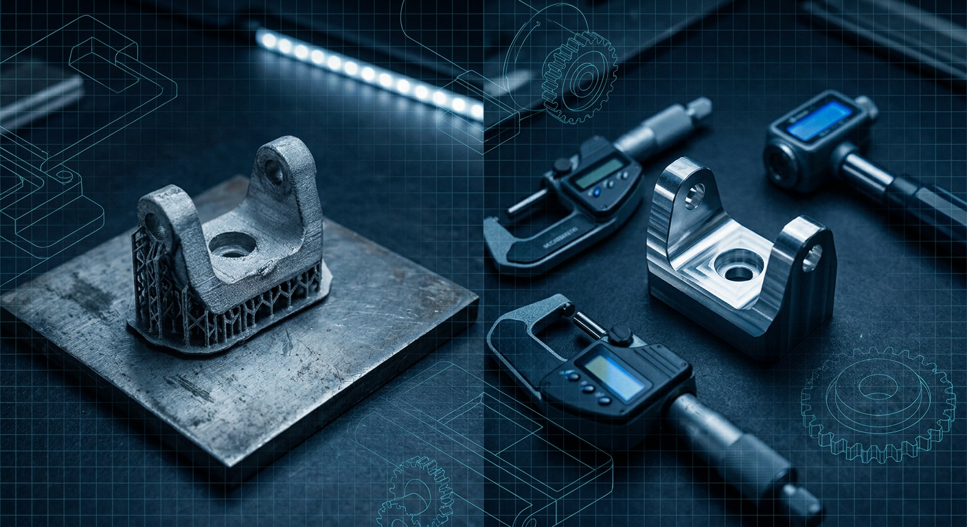
Nikon recently took an impairment charge of roughly 90 billion yen, or about 575 million dollars, primarily against its additive manufacturing business. The writedown lands barely two years after Nikon completed its 622 million euro takeover of German metal 3D printing pioneer SLM Solutions. In regulatory filings and investor updates, Nikon pointed to an intensifying competitive environment and downgraded market expectations. In plain terms, the commercial growth curve that venture capitalists and equipment vendors projected for Laser Powder Bed Fusion (LPBF) simply did not materialize on the factory floor.
For mechanical design engineers, roboticists, and mechanism developers, this financial adjustment is an essential reality check. Over the last decade, hardware startups and R&D labs have been flooded with marketing showing organic, generative metal brackets that look like bird skeletons. The sales pitch promised that additive manufacturing would eliminate machining constraints, consolidate fifty-part assemblies into a single monolithic print, and make tooling obsolete.
When you leave the rendering software and step onto the shop floor, the physics and economics tell a different story. If you are building high-speed linkages, robotic arms, or precision actuator housings, uncritical reliance on metal 3D printing often inflates unit costs by 400 percent while introducing geometric instability that destroys bearing fits. To build reliable mechanisms within budget, engineering teams must understand why metal additive failed to displace subtractive machining and where the real operational costs live.
The Illusion of Free Complexity in Dynamic Mechanisms
Additive manufacturing vendors love to repeat the phrase that complexity is free. For static decorative parts or low-stress brackets in non-critical orientations, complex geometry does not change the laser scan time drastically. But in dynamic mechanisms, complexity is never free. Kinematic assemblies do not care about how organic a part looks. They care about datum consistency, axial alignment, structural stiffness under reversing loads, and predictable fatigue life.
A structural robotic joint, such as an elbow yoke or a wrist carrier, must maintain precise geometric tolerances under high torque. Deep-groove ball bearings, crossed-roller bearings, and strain wave gear sets require bearing bore concentricity within 0.008 mm to 0.012 mm and face perpendicularity under 0.010 mm. Runout outside these limits increases friction, spikes motor current, induces backlash, and shreds gear teeth.
LPBF printers cannot hit these tolerances out of the powder bed. A well-tuned industrial LPBF system printing AlSi10Mg or Scalmalloy yields an as-printed dimensional tolerance of roughly plus or minus 0.1 mm to 0.2 mm over a 150 mm span, with a surface roughness (Ra) between 6 and 15 micrometers. An as-printed hole is not a bearing bore. It is an irregular, rough cavity. Every critical datum, bearing shoulder, and fastener thread must be post-machined on a CNC mill. Once you accept that secondary machining is non-negotiable, the economic equation flips.
The Real Post-Processing Pipeline of LPBF
When evaluating a metal 3D printed component, CAD models hide more than half of the manufacturing workflow. The printer build time is merely step one in a long, capital-intensive manufacturing chain.
[CAD Mesh] -> [Build Prep / Supports] -> [Laser Powder Fusion]
                   |                              |
[Final Inspection] <- [5-Axis CNC Post-Mill] <- [HIP / Furnace] <- [Wire EDM / Cutoff]
Consider the mandatory steps required to produce a functional 6061- or 7075-equivalent structural robot link using LPBF:
Support Structure Design and Sintering: To prevent internal residual stresses from curling the part off the build plate, engineers must anchor overhangs with sacrificial support structures. These supports consume expensive metal powder, add laser sintering hours, and leave rough witness marks that require manual de-burring or blending.
Stress Relief and Thermal Processing: The extreme thermal gradients of localized laser melting induce severe residual stresses. If you cut the part off the build plate immediately, it will warp unpredictably, relieving internal tension by distorting bearing centers. The entire build plate must go into an inert atmosphere furnace for hours to anneal or stress-relieve the alloy before separation.
Separation via Wire EDM: Heavy metal parts cannot simply be snapped off the plate. They are typically severed using Wire Electrical Discharge Machining (Wire EDM) or industrial band saws, tying up another high-cost machine tool.
Custom Fixturing for Post-Machining: This is where generative, organic designs become a nightmare for machinists. A standard prismatic billet can be clamped securely in a standard 6-inch vise or a zero-point chuck with parallel jaws. An organic, topology-optimized bracket has no flat reference datums, no parallel clamping faces, and flexible thin walls. Machining bearing bores to an H7 fit requires engineering custom 3D-printed soft jaws or multi-part potted fixtures just to hold the organic part rigid against milling cutting forces without vibrating or deflecting.
Inspection and Porosity Risk: LPBF parts carry the persistent risk of subsurface micro-porosity and lack-of-fusion defects. For aerospace flight parts, this requires Computed Tomography (CT) scanning or ultrasonic inspection. In robotics, a hidden void near a high-stress bearing shoulder can cause sudden fatigue failure during high-speed emergency stops.
Cost and Cycle Breakdown: LPBF versus 5-Axis Billet CNC
To see why Nikon had to write down SLM Solutions, you only need to evaluate the cost breakdown of a production run for a mid-sized robot joint. The following comparison evaluates a structural robotic actuator housing (envelope: 140 mm x 120 mm x 95 mm, featuring two precision bearing bores, a planetary gearbox mount, and weight-relief pockets).
Unit Cost and Cycle Comparison (Batch of 25 Units)
The metrics below represent an illustrative composite based on real shop-floor data from contract machining facilities, industrial LPBF service bureaus, and production toolroom logs.
| Manufacturing Metric | AlSi10Mg LPBF (Quad-Laser) + CNC Finish | Billet 7075-T6 (5-Axis CNC Milling) | Difference / Penalty |
|---|---|---|---|
| Raw Stock / Powder Cost | $65 (Powder + scrap/re-sieving loss) | $28 (150x130x105 mm 7075 billet) | LPBF is +132% more expensive |
| Machine Run Time (per part) | 4.2 hours (nest of 6 parts on plate) | 0.65 hours (high-speed roughing + finish) | CNC is 6.4x faster per part |
| Thermal / Heat Treatment | $32 (Atmospheric stress relief run) | $0 (Pre-tempered T6 temper billet) | LPBF requires furnace cycle |
| Plate Cutoff (Wire EDM) | $22 per part | $0 (Drop tab or standard 2nd op) | LPBF requires EDM setup |
| Fixturing & Soft Jaw Setup | $450 (Dedicated contoured soft jaws) | $80 (Standard dovetail or vise prep) | LPBF fixturing is 5.6x costlier |
| CNC Post-Machining Cycle | 0.45 hours (Dialing in datums + bores) | Included in primary 5-axis run | LPBF requires manual datum probing |
| As-Finished Tensile Yield | ~230 to 260 MPa (AlSi10Mg heat treated) | ~480 to 505 MPa (7075-T6 wrought) | 7075-T6 has nearly 2x yield strength |
| Total Cost Per Unit (25 run) | $385.00 | $112.00 | LPBF is 3.4x the unit cost |
| Total Turnaround Time | 14 to 18 business days | 3 to 5 business days | Subtractive is 3x faster |
When hardware startup founders see this breakdown, the romantic appeal of metal 3D printing collapses. Even if powder bed fusion gets twenty percent faster, you are still pairing an expensive additive cycle with a difficult, customized subtractive setup. 7075-T6 billet aluminum is not just cheaper; it provides double the yield strength of cast-like AlSi10Mg, has known S-N fatigue curves, and comes with zero internal porosity.
The Organic Mesh Trap in Kinematic Systems
Beyond raw manufacturing cost, there is a fundamental CAD modeling problem that plagues generative additive workflows: dead geometry.
Most generative design tools output raw triangulated meshes (STLs) or dense boundary-representation (B-rep) conversions with thousands of uncontrollable non-uniform rational B-spline (NURBS) surface patches. Once generated, this geometry loses its parametric history. If a physical testing session reveals that the actuator output shaft deflects by 0.04 mm during peak acceleration, an engineer cannot simply edit a sketch dimension to add a 2 mm stiffening rib or shift a bearing shoulder by 1.5 mm. The mesh is locked.
In mechanism design, geometry must remain alive and tightly coupled to the kinematic simulation. A robotic linkage is not an isolated art piece. It interacts with linkages upstream and downstream:
- It must clear dynamic sweep envelopes of adjacent wiring harnesses and pneumatic routing.
- It must permit line-of-sight access for torque wrenches during factory assembly.
- It must accommodate hard stops, sensor mounting brackets, and shim packs for preload adjustment.
When generative tools deliver organic shapes that cannot be parametrically modified, mechanical designers spend days in CAD trying to reverse-engineer surface lofts just to add a flat boss for an inductive proximity sensor. What was supposed to be an automated design process turns into an unmaintainable bottleneck.
Traditional Generative AM Trap:
[Parametric Sketch] -> [Black-Box Solver] -> [Dense Uneditable Mesh] -> [Warped Print] -> [Manual Fixture Hell]

Functional Mechanism Workflow:
[Kinematic Requirements] -> [Parametric Param-Model] -> [Finite Element Check] -> [Standard 5-Axis Path]
When Metal Additive Actually Works
None of this means metal additive manufacturing is useless. It means its economic niche is far narrower than equipment manufacturers claimed when raising venture rounds. Metal LPBF earns its keep only when a part meets three strict engineering criteria:
Internal, Non-Machinable Fluid Channels: Conformal cooling passages in rocket combustion chambers, high-pressure hydraulic manifolds with curved internal galleries, or complex heat exchangers. Subtractive tools cannot drill curved, branching channels through solid metal.
Radical Mass-to-Orbit Value: In aerospace satellite structures or deep-space propulsion where saving a single kilogram is worth thousands of dollars in launch payload capacity, the high unit cost of LPBF is easily justified.
Biocompatible Micro-Porosity: Orthopedic implants (such as titanium hip cups) that require trabecular, porous surface structures to encourage human bone ingrowth.
If a component does not have internal hydraulic channels, is not launching on a rocket, and is not going inside a patient's femur, metal 3D printing is almost certainly the wrong commercial choice. For structural robotics, dynamic linkages, test fixtures, and machine tools, high-speed 5-axis CNC machining from standard wrought alloys (6061-T6, 7075-T6, 4140 steel) wins on unit cost, stiffness, lead time, and dimensional reliability.
A Decision Framework for Mechanism Designers
Before specifying LPBF for any structural or kinematic component, run your design through this sequential engineering filter:
                                [New Part Design]
                                       |
                   Is there an internal enclosed void or
                    conformal cooling channel required?
                                  /          \
                              (YES)          (NO)
                                |              |
                       Evaluate Metal AM       Can a 5-axis mill reach all
                                              critical functional features?
                                                /                      \
                                            (YES)                      (NO)
                                              |                          |
                                       Use 5-Axis CNC           Split into 2-piece
                                      from 7075 Billet          pinned assembly
1. The Tooling Accessibility Rule
Can a standard 5-axis machining center with a 30-degree tool tilt reach every structural feature using standard-length end mills? If yes, keep it subtractive. If a feature is shielded, evaluate whether splitting the part into two dowel-pinned, bolt-together halves is cheaper than printing. In 90 percent of mechanism use cases, a split assembly with ground dowel pins delivers higher stiffness and lower cost than a single monolithic print.
2. The Datum and Fixturing Audit
Identify the primary, secondary, and tertiary datums needed to machine the bearing bores and mounting flanges. Does the component have at least two flat, mutually perpendicular reference faces that can be probed by an automated touch probe (like a Renishaw)? If the generative geometry only provides curved, freeform surfaces, you will spend thousands of dollars on custom inspection gauges and machining fixtures.
3. The Thermal Deflection Reality Check
Does the part have drastic transitions between thick structural bosses (e.g., 25 mm thick) and thin generative web walls (e.g., 2 mm thick)? In LPBF, differential cooling rates across these section changes cause severe localized stress concentrations and part warping during laser exposure. If the design cannot maintain uniform wall thicknesses, scrap rates will be high.
4. Dynamic Mass versus Static Mass
Topology optimization software usually minimizes mass under static load vectors. But robotic linkages experience rapidly reversing dynamic loads, gyroscopic moments, and vibrational harmonics. A thin, lattice-filled generative link might have high static strength in FEA, but low natural frequencies, leading to destructive resonance during high-speed trajectory tracking. Solid-webbed CNC parts with continuous grain structure exhibit superior damping and predictable modal behavior.
What this means for Mexaio AI
Hardware design tools must stop treating mechanical components as decorative statues. Mechanism engineers do not need disconnected text-to-3D tools that generate non-parametric meshes that look impressive in a pitch deck but cannot hold a bearing fit or pass through a CNC toolpath generator.
The real future of engineering software lies in synthesis that understands constraints, fits, kinematic loops, and shop-floor manufacturing limits. Generative kinematics must output fully parametric CAD models, complete with editable feature trees, industry-standard GD&T datums, and real tool clearance verification. Tools like Mexaio AI focus on this exact reality: delivering parametric, editable, simulation-checked mechanisms that respect how metal is actually cut, clamped, and assembled on the factory floor.
Direct Answer: The Economic Reality of Metal AM
Question: What does Nikon's 575 million dollar SLM Solutions writedown tell mechanical designers about the economics of metal additive manufacturing?
Answer: It demonstrates that laser powder bed fusion is not a universal replacement for subtractive machining. Metal AM remains an expensive, niche process restricted to aerospace fluidics, medical implants, and un-machinable internal cavities. For structural robotics and moving mechanisms, 5-axis CNC machining of standard wrought alloys delivers twice the yield strength, higher precision, faster turnarounds, and roughly one-third the total cost once fixturing and post-machining bearing bores are included.
Sources
- 3D Printing Industry report on Nikon SLM Solutions impairment charges: https://3dprintingindustry.com/news/nikon-writes-down-%C2%A590bn-on-slm-solutions-as-metal-3d-printing-growth-expectations-reset-248788/
- Nikon SLM Solutions technical capabilities and multi-laser platforms: https://nikon-slm-solutions.com/
- NIST research on additive manufacturing microstructures and laser powder bed fusion: https://www.nist.gov/additive-manufacturing
- Markforged metal additive design and manufacturing fundamentals: https://markforged.com/resources/learn/design-for-additive-manufacturing-metals