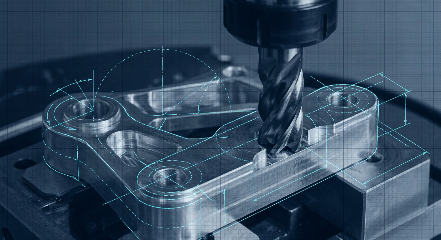
Benchmarking reports across text-to-CAD tools such as Zoo.dev, Leo AI, and AdamCAD show an unmistakable split in the design software market. A prompt can produce a four-bar linkage bracket or a robotic rocker arm in six seconds, presenting a clean shaded rendering in a web viewer. However, when an engineer takes the exported STEP file and loads it into Autodesk Fusion Manufacturing, Mastercam, or Siemens NX CAM to program a 3-axis mill, the workflow halts.
Toolpath generation engines freeze on basic adaptive clearing passes. Automatic hole recognition fails to identify pivot bores. A toolpath that should calculate in two seconds stalls the CAM kernel for three minutes, producing an eighteen-megabyte G-code file stuffed with millions of short linear point moves.
For a mechanical engineer, mechanism designer, or CNC machine shop programmer, this breakdown is not a minor software bug. It is a fundamental architecture clash between computer graphics meshes and precision computer-aided manufacturing. When AI models generate 3D geometry from text, they prioritize visual plausibility over analytical topology. If your team feeds raw AI-generated output straight to machine toolpaths, you risk tool gouges, broken solid carbide end mills, and rejected parts on mechanism linkages where pin fits and center-to-center distances demand sub-twenty-micron accuracy.
The CAM Breakdown: Analytic Geometry vs. Discretized Surface Patches
To understand why CAM software chokes on text-to-CAD exports, you have to look at how toolpath kernels calculate cutting motion. Traditional parametric CAD kernels, such as Parasolid and ACIS, define mechanical parts using boundary representation (B-rep). A cylinder in a native CAD model is not a collection of flat triangles. It is an analytical surface defined by an exact radius, a continuous vector axis, and two planar bounding loops.
When a CAM post-processor sees an analytical cylinder, it generates circular arc commands using G02 (clockwise arc) and G03 (counterclockwise arc) interpolation. The CNC controller takes these arc commands and executes a smooth, continuous circular motion, keeping constant surface speed and uniform chip load across the cutting edge of the tool.
Text-to-CAD engines frequently work backward from diffusion models, neural radiance fields, or signed distance functions that output polygon meshes. Even when these tools export a STEP file, many wrap an analytic B-rep container around a faceted mesh or a dense quilt of non-uniform rational B-spline (NURBS) surface patches.
To the human eye inspecting the part on a CAD screen, the hole looks round. To the CAM engine, the bore consists of 64 or 128 tiny planar facets stitched together with micro-gaps and mismatched surface normal vectors.
When the CAM kernel attempts to calculate an adaptive roughing or helical bore toolpath on faceted surfaces, three critical failures occur:
- Feature recognition failure: The CAM software cannot find a cylindrical face ID, meaning automated hole-making cycles (G81 drilling, G83 peck drilling, and G76 fine boring) cannot initialize.
- G-code bloat: Because there is no true arc, the post-processor cannot write G02 or G03 commands. It converts the circle into thousands of tiny G01 linear segments with chord lengths under 0.05 mm.
- Kernel timeouts and crashes: The CAM surface-slicing algorithm tries to calculate tool contact points across hundreds of non-tangent facet edges, triggering memory leaks or outright software crashes.
Feature Tree Loss and Linkage Bore True Position
In mechanism design, a linkage is only as good as its pivot geometry. Consider a basic bellcrank or a drop link in a parallel robot. The critical engineering requirements are not the decorative organic curves on the outer ribbing. The critical parameters are the center-to-center distance between the two pin bores, the cylindrical runout of each bore, and the perpendicularity of the bore axes relative to the datum face.
[ AI Text Prompt ] --> [ Polygonal Mesh / Quilted Spline ]
                              |
                              v
                 [ Pseudo-STEP Boundary Export ]
                              |
                              v
   +--------------------------+--------------------------+
   |                                                     |
   v                                                     v
[ Autodesk Fusion / Mastercam ]             [ 3-Axis CNC Controller ]
- 0 recognized hole features                 - Starved data buffer (DNC lag)
- 18 MB linear G01 point cloud               - Machine shudder & axis vibration
- Stalled helical interpolation              - Faceted H7 bore out-of-round
When a human designer models a linkage in Creo Parametric, SolidWorks, or Inventor, the model retains an explicit feature tree. The two pivot holes are created as dedicated hole features referencing a shared datum sketch. When this model enters CAM, the CAM programmer can click the cylindrical face, set an ISO H7 tolerance (+0.018/-0.000 mm for a 12 mm pin), and automatically generate a center drill, rough drill, and semi-finish circular pocket followed by a precision reamer or single-point boring bar cycle.
Text-to-CAD engines destroy design intent. Because there is no parametric sketch history or constraint solver backing the output geometry, the two bores do not share an analytical centerline. The AI generates the two holes as isolated negative volume cutouts.
When exported, the axes of these holes are frequently out of parallel by 0.05 to 0.15 degrees, and their cross-sections deviate from true roundness by tens of microns across the faceted boundaries. If you machine that linkage using an approximate 3D surface contouring toolpath instead of a dedicated boring cycle, the hole will not hold an H7/g6 running fit. The pin will bind, friction will spike, and the mechanism will stall under load.
Receipts Block: Toolpath and Machining Benchmarks
The following benchmark data compares toolpath generation performance, G-code volume, and physical machining results across three CAD formats for a 120 mm aluminum 6061-T6 mechanism rocker arm with dual 12 mm pivot bores.
Note: This data is an illustrative composite based on standard 3-axis CNC milling operations in Autodesk Fusion CAM running on a modern quad-core workstation and posted to a Haas VF-2 CNC controller using a standard Haas NextGen post-processor.
| Geometry Source Format | CAM Toolpath Calculation Time | Post-Processed G-Code Size | Feature Auto-Recognition | Machined Bore Roundness Error | Machined Surface Finish (Ra) |
|---|---|---|---|---|---|
| Native Parametric B-Rep (SolidWorks / Creo STEP AP214) | 1.8 seconds | 42 KB (840 lines) | 100% (Drill, Helical Bore, Chamfer) | 0.004 mm (Within H7 tolerance) | 0.6 µm (Mirror finish) |
| Direct Text-to-CAD STEP (Zoo / Leo AI Export) | 48.2 seconds | 14.8 MB (312,000 lines) | 0% (Manual 3D surface selection required) | 0.048 mm (Fails H7 tolerance) | 2.8 µm (Visible facet cusps) |
| Converted Mesh-to-Solid (OBJ/STL converted via CAD B-rep) | 182.0 seconds (Kernel hung once) | 28.4 MB (590,000 lines) | 0% (Unusable for standard hole cycles) | 0.082 mm (Severe out-of-round) | 4.1 µm (Heavy micro-faceting) |
Looking at the numbers reveals why machine shops reject these files. The native parametric model generates 42 kilobytes of clean, readable G-code that executes smoothly on the machine tool. The direct text-to-CAD STEP file balloons to nearly 15 megabytes because every curved surface and round bore is broken into hundreds of thousands of linear micro-vectors.
When a CNC controller attempts to read 300,000 lines of G01 moves at a feed rate of 3,000 mm/min, it hits data buffer starvation. The controller cannot process the incoming coordinate blocks fast enough to maintain continuous motion. The machine decelerates, pauses for milliseconds, accelerates, and pauses again. This shuddering creates chatter marks on the workpiece, ruins surface finish, and can chip the cutting edge of carbide end mills.
Shop Floor Failure Modes on Mechanism Linkages
When mechanism geometry with broken surface definitions makes it past the CAM programmer and onto the shop floor, real hardware failures follow. Mechanism parts are uniquely sensitive to these errors because they contain moving interfaces, tight pin clearances, and dynamic load paths.
1. Bore Polygonization and Pin Binding
A standard dowel pin or ball bearing requires a continuous round fit. A 12 mm ball bearing outer ring pressed into a 28 mm bore requires an M7 or N7 press fit, holding roundness within 0.008 mm.
When a text-to-CAD faceted surface is cut with a ball end mill using 3D surface contouring, the bore ends up as a 64-sided polygon. When the machinist attempts to press the bearing into the housing on an arbor press, the bearing ring contacts only the high apex ridges of the facets. The bearing outer race distorts into a wavy profile, pinching the internal steel balls, causing immediate bearing preload failure, excessive friction, and premature wear.
2. Toolpath Gouging at Non-Manifold Edges
Text-to-CAD generators often produce micro-voids, inverted surface normal vectors, or zero-thickness geometry at the intersection where a structural linkage rib joins a pivot boss. When a CAM 3D adaptive roughing algorithm calculates the tool envelope, it checks for collisions between the tool flutes, tool shank, and the part model.
If two surface patches overlap or intersect with inverted normals, the CAM algorithm misinterprets which side of the surface contains raw material and which side is void. In benign cases, the CAM software throws a computation error and stops. In severe cases, the CAM software generates a toolpath that drives a 10 mm end mill straight through the linkage wall, destroying the part and potentially damaging the machine spindle.
3. Center Distance Drift Across Pivot Linkages
In a robotic four-bar linkage, the mechanical advantage and velocity ratio depend entirely on the precision of the distance between pin centers. If a mechanism has a nominal link length of 150.000 mm, a drift of 0.150 mm across the axis will alter the kinematic end-effector path, cause joint binding at dead-center positions, and overload the drive actuators.
Because text-to-CAD tools do not construct geometry from shared datum coordinate systems, the apparent center of a faceted hole shifts depending on which vertices the CAM software selects to construct a toolpath. A CAM programmer attempting to manually pick points on an AI-generated mesh can easily misalign the true center by 0.05 to 0.12 mm. What looked like a valid linkage in a browser render becomes a binding, overheating assembly when bolted together on the bench.
The Pre-CAM Evaluation Checklist for Mechanism Designers
If your engineering workflow uses text-to-CAD or generative geometry to explore mechanism concepts, you must implement a strict verification gate before exporting files to CAM. Never send raw text-to-CAD STEP or STL files directly to an external machine shop or your internal CNC department.
Use this five-step checklist to filter out dead visual geometry before programming toolpaths:
- Analytical Surface Audit: Open the exported STEP file in your CAD environment (SolidWorks, Creo, or NX) and run an entity check. Click on cylindrical bore faces. If the software highlights the entire cylinder as a single analytical face, it is machinable. If the cylinder is split into dozens of vertical strips or surface patches, quarantine the model.
- Datum and Centerline Verification: Verify that every moving joint bore has an active, accessible centerline axis. Check that the axis is perfectly perpendicular (within 0.01 mm over 50 mm) to the mounting base datum. If the axis cannot be selected for a geometric dimensioning and tolerancing (GD&T) datum frame, it will not support precision boring cycles.
- Non-Manifold and Mesh Edge Inspection: Run an automated geometry repair check (such as
Import Diagnosticsin SolidWorks orExamine Geometryin NX). Check for zero-thickness walls, self-intersecting loops, and unstitched surface boundaries where linkage webs meet mounting bosses. - Toolpath Post-Processing Inspection: After generating your CAM toolpaths, open the resulting G-code file in a text editor. Search for G02 and G03 commands on your finishing passes. If your helical bore operations contain only thousands of G01 lines and zero G02/G03 arc commands, recalculate the operation using an analytical tool boundary or remodel the bore.
- Center-to-Center Distance Audit: Measure the distance between mechanism pivot centerlines using the minimum distance evaluation tool. Compare the nominal dimension against your kinematic synthesis equations. If the CAD model deviates from your mathematical kinematic targets by more than your shop tolerance, do not attempt to compensate inside CAM.
                  [ Incoming AI CAD Geometry ]
                               |
                               v
                  [ Step 1: Analytical Surface Audit ]
                  - True cylinder face detected? ----> NO  --> [ Remodel in Parametric CAD ]
                               | YES
                               v
                  [ Step 2: Axis & Datum Alignment ]
                  - Axes perpendicular & parallel? --> NO  --> [ Remodel in Parametric CAD ]
                               | YES
                               v
                  [ Step 3: Geometry Diagnostics ]
                  - Zero-thickness or bad normals? --> YES --> [ Repair Topology ]
                               | NO
                               v
                  [ Step 4: CAM Arc Output Check ]
                  - G02/G03 present in post code? ---> NO  --> [ Re-anchor Toolpath to Datum ]
                               | YES
                               v
                  [ Step 5: Kinematic Center Check ]
                  - Linkage centers match math? -----> NO  --> [ Adjust Sketch Offsets ]
                               | YES
                               v
                  [ APPROVED FOR CNC PRODUCTION ]
Parametric Kinematics vs. Dead Mesh Geometry
The fundamental issue with early text-to-CAD implementations is a category error: they treat mechanical engineering as a computer graphics problem. In computer graphics, a mesh that looks convincing when rendered under directional lighting is a successful asset. In mechanism design, visual appearance is secondary. A linkage part is an embodiment of kinematic constraints, load vectors, bearing fits, and manufacturing tolerances.
When a mechanism engineer designs a linkage, every line of geometry represents an explicit operational decision. A 10 mm boss exists to clear a socket head cap screw. A 0.5 mm lead-in chamfer exists to guide a needle roller bearing during press assembly. An H7 bore exists so a ground steel shaft can rotate with minimal radial play and zero binding.
AI design systems that bypass the parametric sketch tree and generate raw boundary hulls eliminate the very metadata that allows CAM software and machine tools to do their jobs. True engineering leverage does not come from generating dead 3D geometry from natural language prompts. It comes from generative systems that construct native, fully constrained, parametric feature trees that solve kinematics first and output production-ready analytical B-rep geometry second.
This principle drives the engineering foundation of Mexaio AI (mexaio.ai), which focuses on parametric kinematic synthesis and constraint-checked geometry rather than unstructured mesh generation. When an AI tool respects the underlying mathematical entities of manufacturing, the output passes through CAM seamlessly, calculates toolpaths in seconds, and cuts cleanly on the shop floor without manual cleanup.
Direct Answer: Why Text-to-CAD Output Crashes CAM
Q: Why does AI text-to-CAD output fail or crash when loaded into CNC CAM software?
A: Text-to-CAD engines typically synthesize 3D geometry using polygon meshes or discretized spline patches rather than native analytical B-rep solids. When CAM kernels attempt to calculate 3D toolpaths on these unstitched, faceted surfaces, they cannot recognize standard features like cylindrical bores or planar datums. This causes kernel timeouts, disables canned drilling and boring cycles (G81/G83), and forces post-processors to convert smooth circular cuts into hundreds of thousands of linear G01 micro-moves, crashing software and causing controller buffer starvation on the machine tool.
What to Watch Next on the Shop Floor
Over the next two quarters, watch how text-to-CAD vendors handle their STEP export pipelines. Several generative startups are moving away from mesh-wrapping techniques and shifting toward native Open Cascade, Parasolid, or custom programmatic CAD generation engines that construct sketch-and-extrude trees directly from code.
Until those engines reliably generate analytical cylinders, true datum faces, and valid kinematic constraints, keep a strict wall between raw AI geometry exports and your CAM programming environment. Treat any AI-generated STEP file as an unverified visual concept until its analytical surfaces, bore roundness, and centerline positions pass inspection on your CAD inspection desk.